Rainbow Electronics MAX1791 User Manual
Page 13
MAX1762/MAX1791
High-Efficiency, 10-Pin µMAX, Step-Down
Controllers for Notebooks
______________________________________________________________________________________
13
rated for +0.5A, -0.9A source/sink capability and
swings from VL to GND.
The internal pulldown transistor that drives DL low is
robust, with a 1
Ω typical on-resistance. This helps pre-
vent DL from being pulled up during the fast rise time of
the inductor node, due to capacitive coupling from the
drain to the gate of the low-side synchronous-rectifier
MOSFET. However, for high-current applications, some
combinations of high-and low-side FETS may cause
excessive gate-drain coupling, which can lead to poor
efficiency, EMI, and shoot-through currents.
An adaptive dead-time circuit monitors the DL output
and prevents the high-side FET from turning on until DL
is fully turned off. The dead time at the other edge (DH
turning off) is determined by a fixed 35ns (typ) internal
delay.
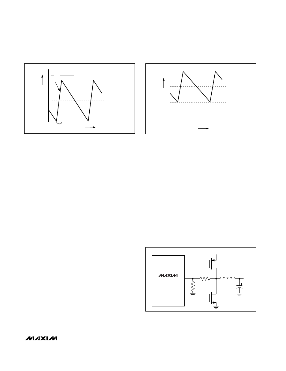
Low-Side Current-Limit Sensing (ILIM)
The current-limit circuit employs a unique “valley” cur-
rent-sensing algorithm that uses the on-state resistance
of the low-side MOSFET as a current-sensing element.
If the current-sense signal is below the current-limit
threshold (-100mV from CS to GND), the PWM is not
allowed to initiate a new cycle (Figure 7). The actual
peak current is greater than the current-limit threshold
by an amount equal to the inductor ripple current.
Therefore, the exact current-limit characteristic and
maximum load capability are a function of the MOSFET
on-resistance, inductor value, and battery voltage.
If greater current-limit accuracy is desired, CS must be
connected to the junction of the low-side switch source
and a current-sense resistor to GND. The current limit
will be 0.1V/R
SENSE
, and the accuracy will be ±10%.
A resistive voltage-divider from the inductor’s switching
mode to ground can be used to adjust the current-limit
sense voltage that appears at CS (Figure 8). Keep the
impedance at this mode low to avoid errors at CS.
POR and Soft-Start
Power-on reset (POR) occurs when V
BATT
rises above
approximately 2V, resetting the fault latch and soft-start
counter and preparing the PWM for operation. UVLO
circuitry inhibits switching until V
VP
rises above 4.1V,
whereupon an internal digital soft-start timer begins to
ramp up the maximum allowed current limit. The ramp
occurs in five steps: 20%, 40%, 60%, 80%, and 100%;
100% current is available after approximately 1.7ms.
Output Undervoltage Protection
The output UVLO function is similar to foldback current
limiting but employs a timer rather than a variable cur-
rent limit. The output undervoltage protection is
enabled 20ms after POR or when coming out of shut-
down. If the output is under 70% of the nominal value,
Figure 6. Pulse-Skipping/Discontinuous Crossover Point
INDUCTOR CURRENT
I
LOAD
= I
PEAK
/2
ON-TIME
0
TIME
I
PEAK
L
V
BATT
- V
OUT
∆i
∆t
=
Figure 7. “Valley” Current-Limit Threshold Point
INDUCTOR CURRENT
I
LIMIT
I
LOAD
0
TIME
I
PEAK
Figure 8. Using a Resistive Voltage-Divider to Adjust Current-
Limit Sense Voltage to 200mV
CS
DH
DL
V
P
MAX1762
MAX1791
1.0k
Ω
V
OUT
1.0k
Ω