Design procedure – Rainbow Electronics MAX1655 User Manual
Page 8
MAX1649/MAX1651
5V/3.3V or Adjustable, High-Efficiency,
Low-Dropout, Step-Down DC-DC Controllers
8
_______________________________________________________________________________________
Modes of Operation
When delivering high output currents, the MAX1649/
MAX1651 operate in continuous-conduction mode. In
this mode, current always flows in the inductor, and
the control circuit adjusts the switch duty cycle to main-
tain regulation without exceeding the switch current
capability (Figure 3). This provides excellent load-tran-
sient response and high efficiency.
In discontinuous-conduction mode, current through the
inductor starts at zero, rises to a peak value, then
ramps down to zero. Although efficiency is still excel-
lent, the output ripple increases slightly, and the switch
waveform exhibits ringing (at the inductor's self-reso-
nant frequency). This ringing is to be expected and
poses no operational problems.
Dropout
The MAX1649/MAX1651 are in dropout when the input
voltage (V+) is low enough that the output drops below
the minimum output voltage specification (see
Electrical Characteristics). The dropout voltage is the
difference between the input and output voltage when
dropout occurs. See the
Typical Operating
Characteristics for the Dropout Voltage vs. Load
Current and Dropout Voltage vs. Temperature graphs.
__________________Design Procedure
Setting the Output Voltage
The MAX1649/MAX1651 are preset for 5V and 3.3V out-
put voltages, respectively; tie FB to GND for fixed-output
operation. They may also be adjusted from 1.5V (the
reference voltage) to the input voltage, using external
resistors R2 and R3 configured as shown in Figure 4. For
adjustable-output operation, 150k
Ω
is recommended for
resistor R3—high enough to avoid wasting energy, yet
low enough to avoid RC delays caused by parasitic
capacitance at FB. R2 is given by:
V
OUT
R2 = R3 x
(
——— -1
)
V
REF
where V
REF
= 1.5V.
When using external resistors, it does no harm to con-
nect OUT and the output together, or to leave OUT
unconnected.
Current-Sense Resistor Selection
The current-sense resistor limits the peak switch cur-
rent to 110mV/R
SENSE
, where R
SENSE
is the value of
the current-sense resistor, and 110mV is the current-
limit trip level (see
Electrical Characteristics).
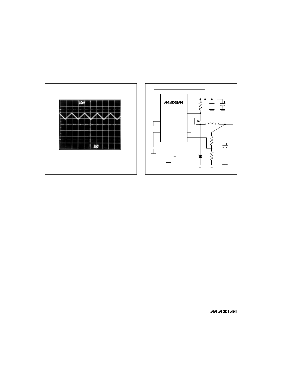
V+ = 10V, I
LOAD
= 1.3A
CIRCUIT OF FIGURE 1, R1 = 75m
Ω
1.5A
0A
1A
2
µ
s/div
Figure 3. MAX1649 Continuous-Conduction Mode, Heavy
Load-Current Waveform (500mA/div)
(
)
MAX1649
MAX1651
V+
CS
GND
5
6
2
8
3
V
IN
C2
330
µ
F
7
1
EXT
OUT
SHDN
4
C3
0.1
µ
F
C4
0.1
µ
F
C1
100
µ
F
R1
0.05
Ω
D1
1N5820
L1
47
µ
H
P1
Si9430
OUTPUT
@ 1.5A
REF
FB
R2
R3
150k
R2 = R3
V
OUT
V
REF
– 1
V
REF
= 1.5V
Figure 4. Adjustable-Output Operation