Table 1. operating configurations – Rainbow Electronics MAX711 User Manual
Page 8
MAX710/MAX711
3.3V/5V or Adjustable,
Step-Up/Down DC-DC Converters
8
_______________________________________________________________________________________
MAX710
SHDN
LX
STBY
N/E
LBO
LBI+
LBI-
REF
PGND
0.1
µ
F
GND
ILIM
PS
OUT
4.7
µ
F
100
µ
F
V
IN
= +1.8V TO +11V
100
µ
F
L1
3/5
MAX710
SHDN
LX
STBY
N/E
LBO
R5 = R6
(V
IN
- V
REF
)
V
REF
R5 = R6 (4.08)
WHEN V
REF
= 1.28V
AND V
IN
= 6.5V
LBI+
LBI-
REF
PGND
0.1
µ
F
GND
ILIM
PS
OUT
R6
R5
4.7
µ
F
100
µ
F
V
IN
= +1.8V TO +11V
100
µ
F
L1
3/5
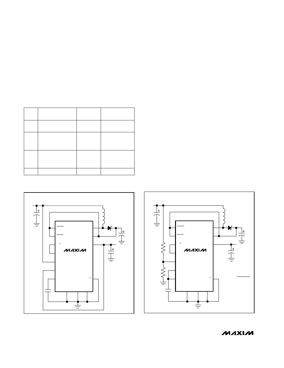
Figure 2a. High-Efficiency Operating Configuration for
V
BATT
< V
OUT
Figure 2b. High-Efficiency Operating Configuration for
V
BATT
< 6.5V
In high-efficiency mode (N/
E
= low), the maximum
input voltage is limited to 7V.
This voltage limitation is
easily overcome, however, by configuring the LBO out-
put to change modes based on input voltage, allowing
an 11V maximum input with high-efficiency configura-
tions. Four operating configurations are described in
Table 1 and in the following subsections.
Configuration 1: High Efficiency, 7V Max V
IN
With N/E connected to GND, when the IC boosts, the
linear regulator operates only as a switch, with mini-
mum forward drop, until V
IN
> V
OUT
(where linear regu-
lation begins). This configuration is limited to no more
than 7V input, but provides best efficiency for battery-
only operation or low-voltage AC adapter usage.
Configuration 2: High Efficiency, V
BATT
< V
OUT
In this configuration, N/E is driven high by LBO when
V
IN
> V
OUT
(Figure 2a). When V
IN
< V
OUT
, the IC
boosts, and the linear regulator operates as a switch,
with minimum forward drop. When V
IN
> V
OUT
, the lin-
ear regulator operates with V
FV
forward drop, while V
PS
increases by V
FV
so that OUT maintains regulation. V
FV
is set inside the IC to approximately 0.5V (at 5V V
OUT
).
When V
IN
is only slightly higher than V
OUT
, conversion
efficiency is poorer than in configuration 1, so configu-
ration 2 is most suitable when the battery voltage is less
than V
OUT
, but the AC adapter output is greater than
V
OUT
.
Up to 11V
2
Up to 11V
4
Up to 11V
3
High efficiency,
V
BATT
< V
OUT
(Figure 2a)
Low noise
High efficiency,
11V, V
BATT
< 6.5V
(Figure 2b)
DESCRIPTION
High efficiency,
7V max V
IN
INPUT
VOLTAGE
Up to 7V
1
NO.
LBO = N/E
LBI- = V
OUT
LBI+ = V
IN
N/E = PS
LBO = N/E
LBI- = REF
LBI+ = R5, R6
CONNECTIONS
N/E = GND
Table 1. Operating Configurations