Step-up dc-dc controllers – Rainbow Electronics MAX773 User Manual
Page 7
MAX770–MAX773
5V/12V/15V or Adjustable, High-Efficiency,
Low I
Q
, Step-Up DC-DC Controllers
_______________________________________________________________________________________
7
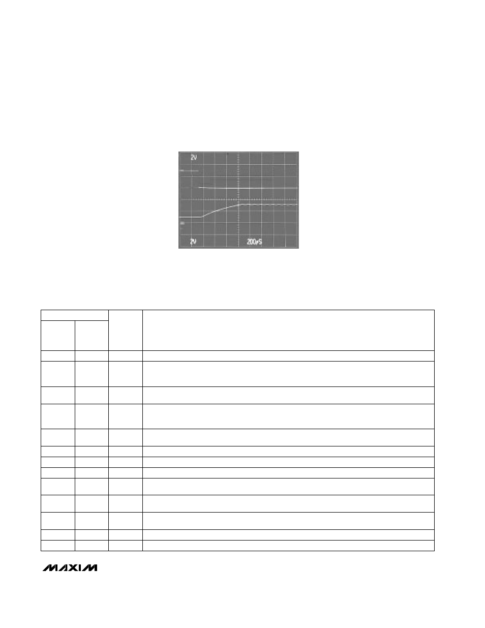
V
IN
= 3V, I
OUT
= 0.5A
A: SHDN, 2V/div
B: V
OUT
, 2V/div
MAX770
EXITING SHUTDOWN
A
B
0
0
200
µ
s/div
______________________________________________________________Pin Description
____________________________Typical Operating Characteristics (continued)
(Circuit of Figure 2a, T
A
= +25°C, unless otherwise noted.)
PIN
NAME
FUNCTION
MAX773
1
—
EXT
Gate drive for external N-channel power transistor
2
3
V+
3
6
FB
4
7
SHDN
5
8
REF
6
—
AGND
Analog ground
7
9
GND
High-current ground return for the output driver
8
11
CS
—
1
V12
—
2
V5
MAX770
MAX771
MAX772
Power-supply input. Also acts as a voltage-sense point when in bootstrapped mode for the
MAX770/MAX771/MAX772, or as a shunt regulator when SGND is connected to ground for the
MAX773. Bypass to SGND with 0.1
µ
F when using the shunt regulator.
Feedback input for adjustable-output operation. Connect to ground for fixed-output operation. Use
a resistor divider network to adjust the output voltage. See
Setting the Output Voltage
section.
Active-high TTL/CMOS logic-level shutdown input. In shutdown mode, V
OUT
is a diode drop
below V+ (due to the DC path from V+ to the output) and the supply current drops to 5
µ
A
maximum. Connect to ground for normal operation.
1.5V reference output that can source 100
µ
A for external loads. Bypass to GND with 0.1
µ
F.
The reference is disabled in shutdown.
Positive input to the current-sense amplifier. Connect the current-sense resistor between CS and GND.
Input sense point for 12V-output operation. Connect V
OUT
to V12 for 12V-output operation.
Leave unconnected for adjustable-output operation.
Input sense point for 5V-output operation. Connect V
OUT
to V5 for 5V-output operation. Leave
unconnected for adjustable-output operation.
—
4
LBO
—
5
LBI
Input to the internal low-battery comparator. Tie to GND or V+ if not used.
—
10
SGND
Shunt regulator ground. Leave unconnected if the shunt regulator is
not
used.
Low-battery output is an open-drain output that goes low when LBI is less than 1.5V. Connect to V+
through a pull-up resistor. Leave floating if not used. LBO is high impedance in shutdown mode.