Step-up dc-dc controllers, External transistor, Typical operating characteristics – Rainbow Electronics MAX773 User Manual
Page 12: Low-voltage start-up oscillator
MAX770–MAX773
turned on, it stays on until either 1) the maximum on-
time one-shot turns it off (typically 16µs later), or 2) the
switch current reaches the peak current limit set by the
current-sense resistor.
To increase light-load efficiency, the current limit for the
first two pulses is set to one-half the peak current limit.
If those pulses bring the output voltage into regulation,
the error comparator holds the MOSFET off and the
current limit remains at one-half the peak current limit. If
the output voltage is still out of regulation after two
pulses, the current limit for the next pulse is raised to
the peak current limit set by the external sense resistor
(see inductor current waveforms in the
Typical
Operating Characteristics
).
The MAX770–MAX773 switching frequency is variable
(depending on load current and input voltage), causing
variable switching noise. However, the subharmonic
noise generated does not exceed the peak current limit
times the filter capacitor equivalent series resistance
(ESR). For example, when generating a 12V output at
500mA from a 5V input, only 180mV of output ripple
occurs using the circuit of Figure 2b.
Low-Voltage Start-Up Oscillator
The MAX770/MAX771/MAX772 feature a low input volt-
age start-up oscillator that guarantees start-up with no
load down to 2V when operating in bootstrapped mode
and using internal feedback resistors. At these low volt-
ages, the supply voltage is not large enough for proper
error-comparator operation and internal biasing. The
start-up oscillator has a fixed 50% duty cycle and the
MAX770/MAX771/MAX772 disregard the error-com-
parator output when the supply voltage is less than
2.5V. Above 2.5V, the error-comparator and normal one-
shot timing circuitry are used. The low voltage start-up
circuitry is disabled if non-bootstrapped mode is select-
ed (FB is not tied to ground).
The MAX773 does not provide the low-voltage 50%
duty-cycle oscillator. Its minimum start-up voltage is 3V
for all modes.
External Transistor
An N-FET power switch is recommended for the
MAX770/MAX771/MAX772.
The MAX773 can drive either an N-channel MOSFET
(N-FET) or an NPN because it provides two separate
5V/12V/15V or Adjustable, High-Efficiency,
Low I
Q
, Step-Up DC-DC Controllers
12
______________________________________________________________________________________
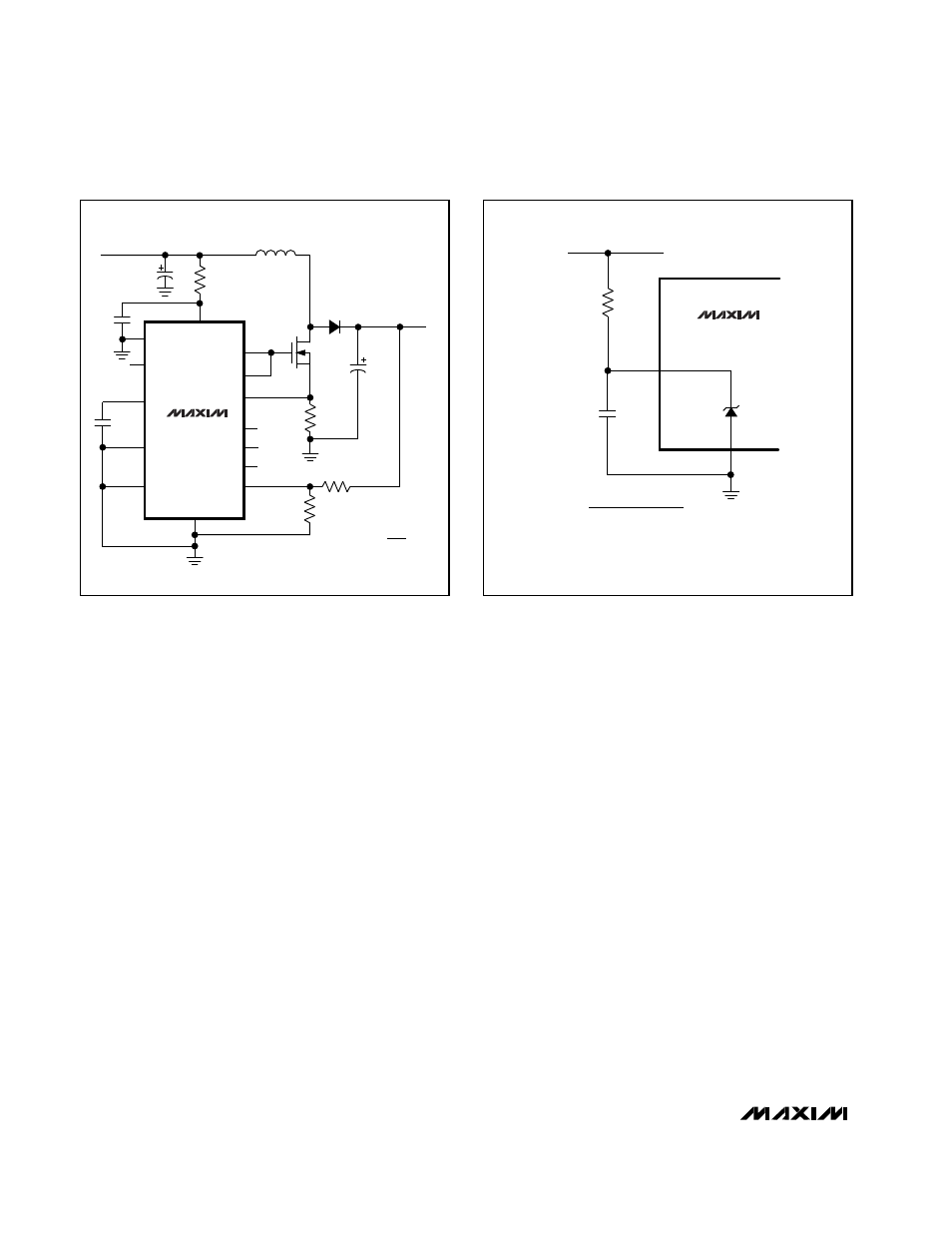
GND
MAX773
C3
0.1
µ
F
v+
EXTL
CS
V5
8
5
7
V15
V12
LBO
REF
LBI
SHDN
4
12
11
2
14
1
9
R
SENSE
1.0
Ω
C4
100
µ
F
D1
MUR115
EXTH
13
3
L1
250
µ
H
V
OUT
= 100V
@ 10mA
SGND
N
10
C1
47
µ
F
FB
6
R2
732k (1%)
R1
11.3k (1%)
Si9420DY
R
SHUNT
3k
C2
0.1
µ
F
V
IN
= 24V TO 28V
V
OUT
V
REF
R2 = (R1)
(
-1
)
V
REF
= 1.5V
MAX773
R
SHUNT
C2
0.1
µ
F
SGND
6V (typ)
V+
V
IN
R
SHUNT =
V
IN (MIN)
- V
SHUNT
(
MAX
)
I
SHUNT
*
*
SEE TEXT FOR I
SHUNT
CALCULATION
3
10
Figure 3e. 100V Output, Shunt Regulator, N-Channel Power
MOSFET
Figure 4. MAX773 Shunt Regulator