Serial interface, Using s sh hd dn n to reduce supply current – Rainbow Electronics MAX1243 User Manual
Page 8
MAX1242/MAX1243
+2.7V to +5.25V, Low-Power, 10-Bit
Serial ADCs in SO-8
8
_______________________________________________________________________________________
Serial Interface
Initialization after Power-Up and
Starting a Conversion
When power is first applied, and if SHDN is not pulled
low, it takes the fully discharged 4.7µF reference
bypass capacitor up to 20ms to provide adequate
charge for specified accuracy. With an external refer-
ence, the internal reset time is 10µs after the power
supplies have stabilized. No conversions should be
performed during these times.
To start a conversion, pull CS low. At CS’s falling edge,
the T/H enters its hold mode and a conversion is initiat-
ed. After an internally timed conversion period, the end
of conversion is signaled by DOUT pulling high. Data
can then be shifted out serially with the external clock.
Using
S
SH
HD
DN
N to Reduce Supply Current
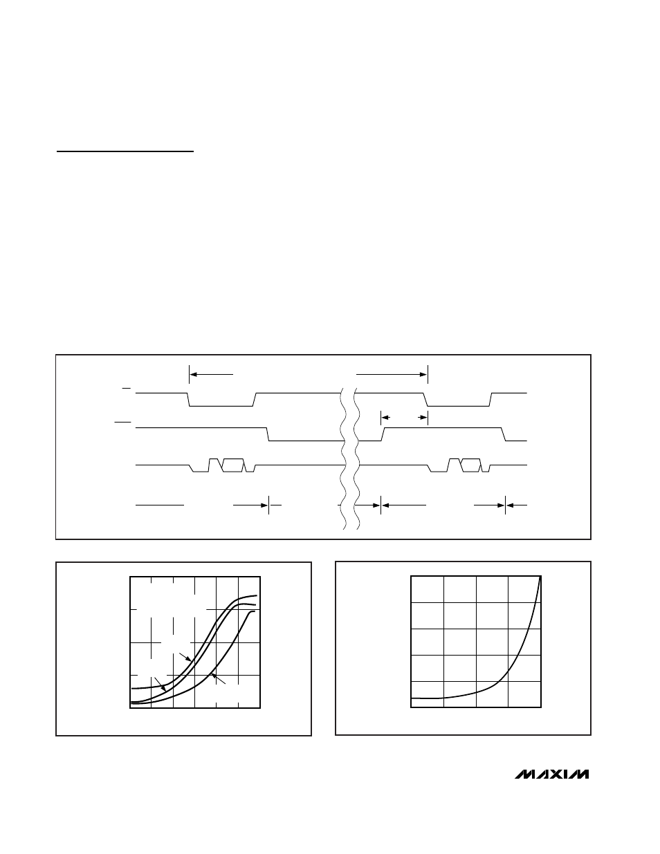
Power consumption can be reduced significantly by
shutting down the MAX1242/MAX1243 between con-
versions. Figure 6 shows a plot of average supply cur-
rent vs. conversion rate. Because the MAX1243 uses
an external reference voltage (assumed to be present
continuously), it “wakes up” from shutdown more quick-
ly, providing lower average supply currents. The wake-
up time, t
WAKE
, is the time from SHDN deasserted to
the time when a conversion may be initiated (Figure 5).
For the MAX1242, this time depends on the time in
shutdown (Figure 7) because the external 4.7µF refer-
ence bypass capacitor loses charge slowly during
shutdown. The MAX1243’s wake-up time is largely
dependent on the external reference’s power-up time. If
the external reference is not shut down, the wake-up
time is approximately 4µs.
10,000
100
1000
1
0.1
1
10
100
1k
10k
100k
10
CONVERSIONS/SEC
SUPPLY CURRENT (
µ
A)
V
DD =
V
REF
R
LOAD
=
∞
, C
LOAD
= 50pF
CODE = 0101010100
MAX1243-fig06
MAX1242
V
DD
= 3V
MAX1242
V
DD
= 5V
MAX1243
V
DD
= 3V
Figure 6. Average Supply Current vs. Conversion Rate
1.0
0.0
0.001
0.01
0.1
1
10
0.8
0.6
0.4
0.2
TIME IN SHUTDOWN
(sec)
POWER-UP DELAY (ms)
MAX1242/43-07
Figure 7. Typical Reference-Buffer Power-Up Delay vs. Time in
Shutdown
COMPLETE CONVERSION SEQUENCE
t
WAKE
POWERED UP
POWERED DOWN
POWERED UP
CONVERSION 0
CONVERSION 1
DOUT
CS
SHDN
Figure 5. Shutdown Sequence