I/o signaling, Write-time slots, Read-time slots – Rainbow Electronics DS2705 User Manual
Page 17: Figure 8. 1-wire initialization sequence, Reset presence pulse
DS2705: SHA-1 Authentication Master
17 of 18
I/O SIGNALING
The 1-Wire bus requires strict signaling protocols to ensure data integrity. The four protocols used in 1-Wire
communication are as follows: the initialization sequence (reset pulse followed by presence pulse), write 0, write 1,
and read data. The 1-Wire bus master initiates all these types of signaling except the presence pulse.
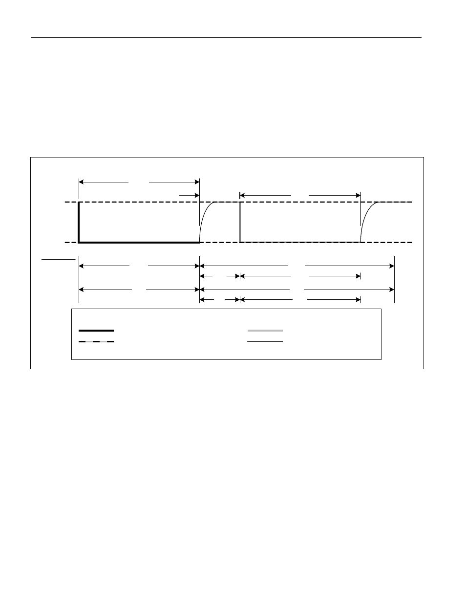
The initialization sequence required to begin any 1-Wire communication is shown in Figure 8. A presence pulse
following a reset pulse indicates that the 1-Wire slave is ready to accept a net address command. The bus master
transmits (Tx) a reset pulse for t
RSTL
. The bus master then releases the line and goes into receive mode (Rx). The
1-Wire bus line is then pulled high by the pullup resistor. After detecting the rising edge on the DQ pin, the slave
waits for t
PDH
and then transmits the presence pulse for t
PDL
.
Figure 8. 1-Wire Initialization Sequence
RESET
PRESENCE PULSE
t
MRSTL
V
PULLUP
GND
680
ms
70ms
40ms
4ms
160ms
16
ms
640ms
Overdrive
Standard
MODE
t
MPDH
t
MPDL
64ms
LINE TYPE LEGEND:
Bus Master active LOW
Device active LOW
Both Bus Master and Device
Resistor pullup
active LOW
WRITE-TIME SLOTS
A write-time slot is initiated when the bus master pulls the 1-Wire bus from a logic-high (inactive) level to a logic-low
level. There are two types of write-time slots: write 1 and write 0. All write-time slots must be t
SLOT
in duration with
a 1
ms minimum recovery time, t
REC
, between cycles. The slave samples the 1-Wire bus line between t
LOW1_MAX
and
t
LOW0_MIN
after the line falls. If the line is high when sampled, a write 1 occurs. If the line is low when sampled, a
write 0 occurs. The sample window is illustrated in Figure 9. 1-Wire Write and Read-Time
Slots. For the bus master
to generate a write 1 time slot, the bus line must be pulled low and then released, allowing the line to be pulled high
less than t
RDV
after the start of the write time slot. For the host to generate a write 0 time slot, the bus line must be
pulled low and held low for the duration of the write-time slot.
READ-TIME SLOTS
A read-time slot is initiated when the bus master pulls the 1-Wire bus line from a logic-high level to a logic-low level.
The bus master must keep the bus line low for at least 1
ms and then release it to allow the slave to present valid
data. The bus master can then sample the data t
RDV
from the start of the read-time slot. By the end of the read-
time slot, the slave releases the bus line and allows it to be pulled high by the external pullup resistor. All read-time
slots must be t
SLOT
in duration with a 1
ms minimum recovery time, t
REC
, between cycles. See Figure 9 and the timing
specifications in the Electrical Characteristics table for more information.