Ac electrical characteristics (v, 25°c) – Rainbow Electronics DS1603 User Manual
Page 8
DS1603
8 of 9
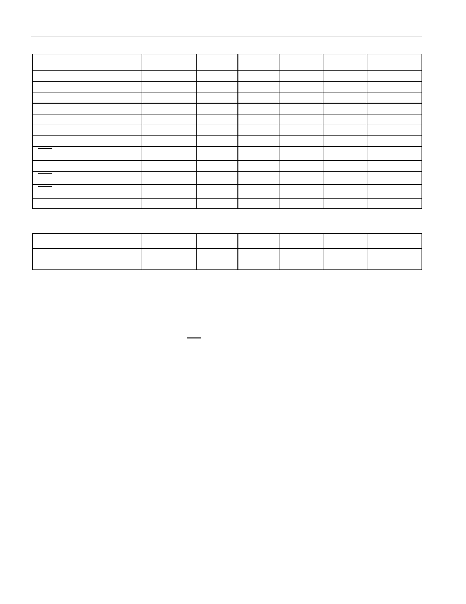
AC ELECTRICAL CHARACTERISTICS (V
CC
= +5V ±10%; 0°C to +70°C)
PARAMETER
SYMBOL
MIN
TYP
MAX
UNITS
NOTES
Data to CLK Setup
t
DC
50
ns
6
CLK to Data Hold
t
CDH
60
ns
6
CLK to Data Delay
t
CDD
200
ns
6, 7, 8
CLK Low Time
t
CL
250
ns
6
CLK High Time
t
CH
250
ns
6
CLK Frequency
f
CLK
DC
2.0
MHz
6
CLK Rise and Fall
t
F,
t
R
500
ns
RST
to CLK Setup
t
CC
100
ns
6
CLK to RST Hold
t
CCH
60
ns
6
RST
Inactive Time
t
CWH
1
µs
6
RST
Low to I/O High-Z
t
RDZ
70
ns
6
CLK High to I/O High- Z
t
CDZ
20
ns
6
(T
A
= +25°C)
PARAMETER
SYMBOL
MIN
TYP
MAX
UNITS
NOTES
Expected Data
Retention Time
t
DR
10
years
10
NOTES:
1) All voltages are referenced to ground.
2) Logic 1 voltages are specified at a source current of 1mA.
3) Logic 0 voltages are specified at a sink current of 4mA.
4) I
CC
is specified with the DQ pin open.
5) I
CC1
is specified with V
CC
at 5.0V and
RST
= GND.
6) Measured at V
IH
= 2.0V or V
IL
= 0.8V.
7) Measured at V
OH
= 2.4V or V
OL
- 0.4V.
8) Load capacitance = 50pF.
9) Battery trip point is the point at which the V
CC
powered counter and the serial port stops operation.
The battery trip point drops below the minimum once the internal lithium energy cell is exhausted.
10) The expected t
DR
is defined as accumulative time in the absence of V
CC
with the clock oscillator
running.
11) Real-time clock modules can be successfully processed through conventional wave-soldering
techniques as long as temperature exposure to the lithium energy source contained within does not
exceed +85
°
C. Post-solder cleaning with water-washing techniques is acceptable, provided that
ultrasonic vibration is not used.