Dc and logic electrical characteristics, Ac electrical characteristics – Rainbow Electronics ADC12081 User Manual
Page 6
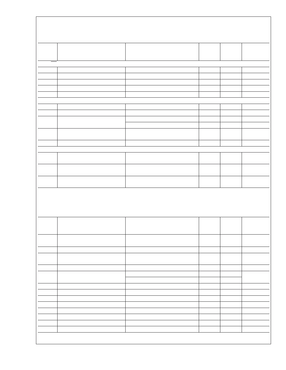
DC and Logic Electrical Characteristics
The following specifications apply for AGND = DGND = DGND I/O = 0V, V
A
= V
D
= V
D
I/O = +5V, PD = +5V, V
REF
= +2.0V,
f
CLK
= 50MHz, C
L
= 50 pF/pin. After Auto-Cal at Temperature. Boldface limits apply for T
A
= T
MIN
to T
MAX
; all other limits
T
A
= T
J
= 25˚C (Note 7) (Note 8) and (Note 9)
Symbol
Parameter
Conditions
Typical
Limits
Units
(Limits)
CLK, OE Digital Input Characteristics
V
IH
Logical "1" Input Voltage
V+ = 5.25V
2.0
V(min)
V
IL
Logical "0" Input Voltage
V+ = 4.75V
0.8
V(min)
I
IH
Logical "1" Input Current
V
IN
= 5.0V
5
µA
I
IL
Logical "0" Input Current
V
IN
= 0V
−5
µA
C
IN
V
IN
Input Capacitance
8
pF
D0 - D11 Digital Output Characteristics
V
OH
Logical "1" Output Voltage
I
OUT
= −1mA
4
V (min)
V
OL
Logical "0" Output Voltage
I
OUT
= 1.6mA
0.4
V (max)
I
OZ
TRI-STATE
®
Output Current
V
OUT
= 3V or 5V
10
µA
V
OUT
= 0V
−10
µA
+I
SC
Output Short Circuit Source
Current
VDDO= 3V, V
OUT
= 0V
−14
mA(min)
−I
SC
Output Short Circuit Sink Current
VDDO= 3V, V
OUT
= V
O
16
mA(min)
Power Supply Characteristics
I
A
Analog Supply Current
PD = VDDO
PD = DGND
2.5
20
4
26
mA(max)
mA(max)
I
D
Digital Supply Current
PD = VDDO
PD = DGND
0.5
1
2
2
mA(max)
mA(max)
Total Power Consumption
PD = VDDO
PD = DGND
15
105
30
140
mW(max)
mW(max)
AC Electrical Characteristics
The following specifications apply for AGND = DGND = DGND I/O = 0V, V
A
= V
D
= V
D
I/O = +5V, PD = +5V, V
REF
= +2.0V,
f
CLK
= 5 MHz, C
L
= 50 pF/pin. After Auto-Cal at Temperature. Boldface limits apply for T
A
= T
MIN
to T
MAX
; all other limits T
A
= T
J
= 25˚C (Note 7) (Note 8) and (Note 10)
Symbol
Parameter
Conditions
Typical
Limits
Units
(Limits)
f
CLK
Clock Frequency
0.5
MHz(min)
5
MHz(max)
Clock Duty Cycle
50
%
t
CONV
Conversion Latency
10.25
Clock
Cycles
t
AD
Aperture Delay Time
3.5
ns
t
OD
Data output delay after rising clk
edge
V
D
I/O = 3V
44
ns
V
D
I/O = 5V
40
t
DIS
Data outputs into Tristate mode
21
nA (max)
t
EN
Data outputs active after Tristate
21
ns (max)
t
WCAL
Calibration request pulse width
3
Tclk(min)
t
RDYC
Ready Low after CAL request
3
Tclk
t
CAL
Calibration cycle
4000
Tclk
t
WPD
Power-down pulse width
3
Tclk(min)
t
RDYPD
Ready Low after PD request
3
Tclk
t
PD
Power down mode exit cycle
4000
Tclk
ADC12081
www.national.com
6