Rainbow Electronics DS1993 User Manual
Page 8
DS1992/DS1993/DS1994
8 of 23
102199
Alarm Registers
The alarm registers for the real-time clock, interval timer, and cycle counter all operate in the same
manner. When the value of a given counter equals the value in its associated alarm register, the
appropriate flag bit is set in the status register. If the corresponding interrupt enable bit(s) in the status
register is set, an interrupt is generated. If a counter and its associated alarm register are write protected
when an alarm occurs, access to the device becomes limited. (See “Status/Control”, “Interrupts”, and the
“Programmable Expiration” sections.)
STATUS/CONTROL REGISTERS (DS1994)
The status and control registers are the first two bytes of page 16 (see “Memory Map”, Figure 4).
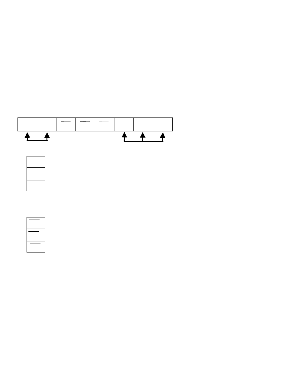
Status Register
7
6
5
4
3
2
1
0
X
X
CCE
ITE
RTE
CCF
ITF
RTF
0200h
Don’t care bits
Read Only
0
RTF
Real-time clock alarm flag
1
ITF
Interval timer alarm flag
2
CCF
Cycle counter alarm flag
When a given alarm occurs, the corresponding alarm flag is set to a logic 1. The alarm flag(s) is cleared
by reading the status register.
3
RTE
Real-time clock alarm flag
4
ITE
Interval timer alarm flag
5
CCE
Cycle counter alarm flag
Writing any of the interrupt enable bits to a logic 0 will allow an interrupt condition to be generated when
its corresponding alarm flag is set (see “Interrupts” section).