Ds1099 low-frequency dual econoscillator, Application information, Chip topology – Rainbow Electronics DS1099 User Manual
Page 6: Package information, Ordering information (continued), Branding information
DS1099
Low-Frequency Dual EconOscillator
Maxim cannot assume responsibility for use of any circuitry other than circuitry entirely embodied in a Maxim product. No circuit patent licenses are
implied. Maxim reserves the right to change the circuitry and specifications without notice at any time.
6
_____________________Maxim Integrated Products, 120 San Gabriel Drive, Sunnyvale, CA 94086 408-737-7600
© 2004 Maxim Integrated Products
Printed USA
is a registered trademark of Maxim Integrated Products.
The divider settings, X
0
and X
1
, are factory pro-
grammed. When placing an order for the DS1099, it is
required to specify X
0
and X
1
. If only one output is used,
it is recommended that the unused output be disabled.
The oscillator outputs are asynchronous. Since the
master oscillator and dividers are free running, even
when both outputs are disabled, the state of the output
when OE becomes active is unknown for up to half an
f
OUT
period. When OE is brought low, the output is
enabled instantaneously. Likewise, if the output is dis-
abled while outputting the low half of a cycle, the out-
put instantaneously is forced high before the current
cycle is completed.
Application Information
Power-Supply Decoupling
To achieve best results, it is highly recommended that
a decoupling capacitor is used on the IC power-supply
pins. Typical values of decoupling capacitors are
0.01µF and 0.1µF. Use a high-quality, ceramic, sur-
face-mount capacitor, and mount it as close as possi-
ble to the V
CC
and GND pins of the IC to minimize lead
inductance.
Chip Topology
TRANSISTOR COUNT: 4221
SUBSTRATE CONNECTED TO GROUND
Package Information
For the latest package outline information, go to
www.maxim-ic.com/DallasPackInfo
.
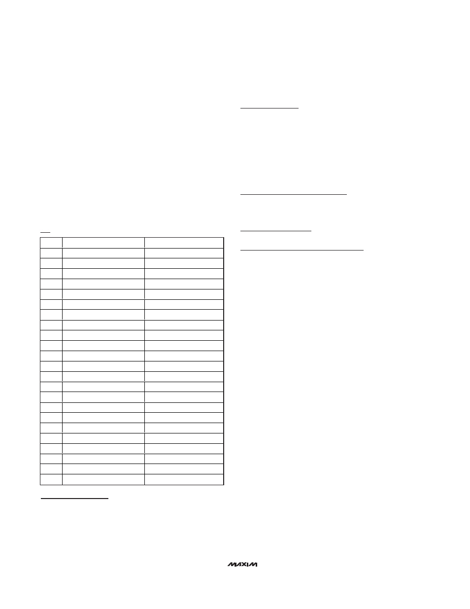
Ordering Information (continued)
ααα
α
DIVISOR
fOUT
A
2
0
1.048MHz
B
2
1
0.524MHz
C
2
2
0.262MHz
D
2
3
0.131MHz
E
2
4
65.50kHz
F
2
5
32.750kHz
G
2
6
16.375kHz
H
2
7
8.187kHz
J
2
8
4.093kHz
K
2
9
2.046kHz
L
2
10
1.023kHz
M
2
11
511.7Hz
N
2
12
255.8Hz
P
2
13
127.9Hz
Q
2
14
63.96Hz
R
2
15
31.98Hz
S
2
16
16Hz
T
2
17
8Hz
U
2
18
4Hz
W
2
19
2Hz
X
2
20
1Hz
Y
2
21
0.5Hz
Z
2
22
0.25Hz
Branding Information
The package branding includes
α
0
and
α
1
on the top
of the package next to or below 1099.