Isd1916 – Rainbow Electronics ISD1916 User Manual
Page 21
ISD1916
Publication Release Date: September 11, 2007
- 21 -
Revision 0
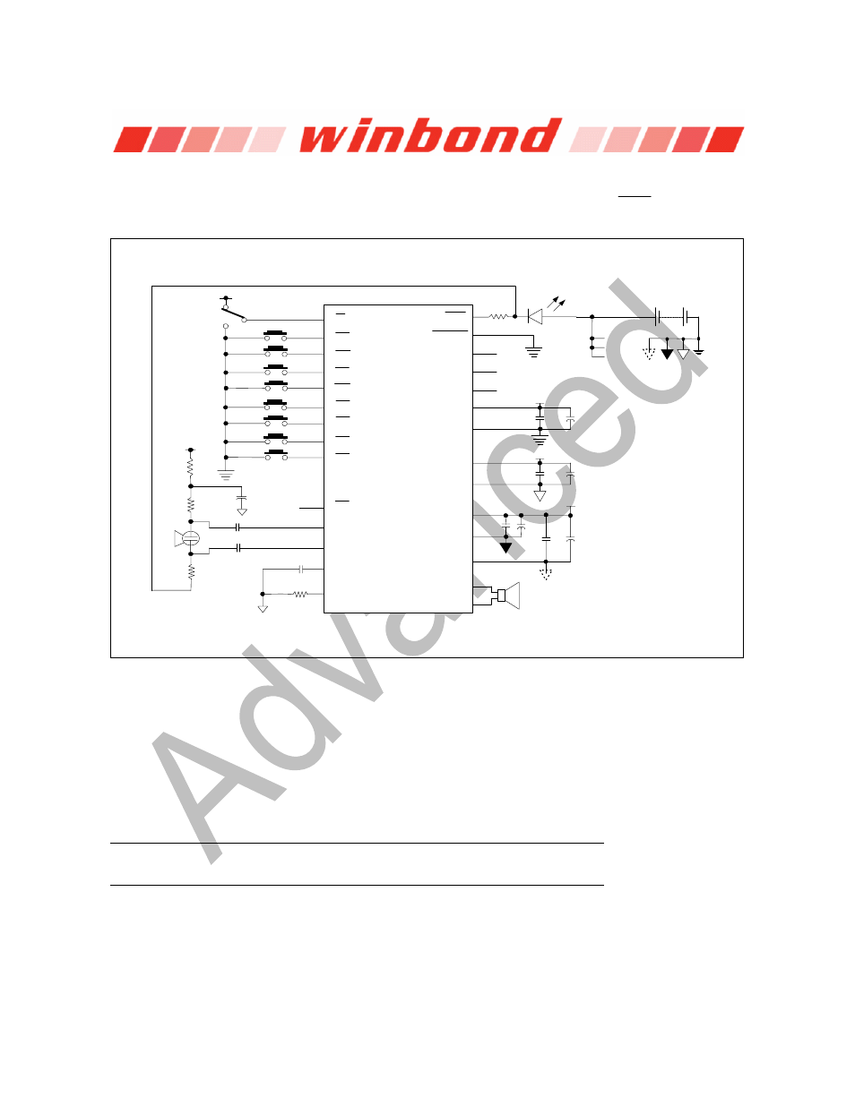
Example #2: Fixed Message Configuration Operations under direct trigger mode (
MODE
)
Rosc*
Speaker
V
CC
4.7 F*
µ
Ω∗
4.7 k
0.1 F*
µ
0.1 F*
µ
4.7 k
Ω∗
4.7 k
Ω∗
4.7 F*
µ
1 k
Ω
D1
0.1 F
µ
µ
10 F
V
CCA
µ
10 F*
V
CCP
0.1 F
µ
µ
10 F*
0.1 F
µ
V
CCA
V
CCD
V
CCP
Vcc Gnd
ISD14B20
FMC1
FMC3
FMC2
M3
M4
M5
M6
M7
M8
M2
R/P
M1
Mic+_AnaIn
Mic-
SP-
AGC
Rosc
SP+
V
SSP1
V
SSP2
FT
V
SSD
V
CCD
V
CCA
V
SSA
V
CCP
MODE
0.1 F
µ
µ
10 F*
V
CCD
LED
V
CC
Good Audio Design Practices
Winbond’s ChipCorder are very high-quality single-chip voice recording and playback devices. To
ensure the highest quality voice reproduction, it is important that good audio design practices on
layout and power supply decoupling are followed. See Application Information links below for details.
Good Audio Design Practices
http://www.winbond-usa.com/products/isd_products/chipcorder/applicationinfo/apin11.pdf
Single-Chip Board Layout Diagrams
http://www.winbond-usa.com/products/isd_products/chipcorder/applicationinfo/apin12.pdf
It is strongly recommended that before any design or layout project starts, the designer should contact
Winbond Sales Rep for the most update technical information and layout advice.