Isd1916, Typical application circuit – Rainbow Electronics ISD1916 User Manual
Page 20
ISD1916
Publication Release Date: September 11, 2007
- 20 -
Revision 0
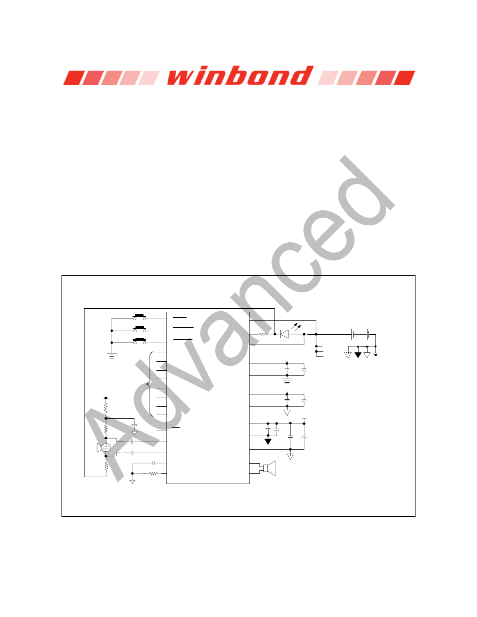
9. TYPICAL APPLICATION CIRCUIT
The following typical application examples on ISD1916 series are for references only. They make
no representation or warranty that such applications shall be suitable for the use specified. It’s
customer’s obligation to verify the design in its own system for the functionalities, voice quality,
current consumption, and etc.
In addition, the below notes apply to the following application examples:
* The suggested values are for references only. Depending on system requirements, they can
be adjusted for functionalities, voice quality and degree of performance.
It is important to have a separate path for each ground and power back to the related terminals to
minimize the noise. Besides, the power supplies should be decoupled as close to the device as
possible.
Also, it is crucial to follow good audio design practices in layout and power supply decoupling. See
recommendations in Application Notes from our websites.
Example #1: Operations via start and end addresses under address trigger mode (
NORM
)
Rosc*
Speaker
V
CC
4.7 F*
µ
Ω∗
4.7 k
0.1 F*
µ
0.1 F*
µ
4.7 k
Ω∗
4.7 k
Ω∗
4.7 F*
µ
1 K
Ω
D1
0.1 F
µ
µ
10 F*
V
CCD
0.1 F
µ
µ
10 F*
V
CCA
µ
10 F*
V
CCP
0.1 F
µ
µ
10 F*
0.1 F
µ
V
CCA
V
CCD
V
CCP
Vcc Gnd
ISD1916
V
SSD
Mic+_AnaIn
Mic-
SP-
V
CCD
AGC
Rosc
V
CCA
SP+
V
SSA
PLAYE
PLAYL
S2
S1
S0
E2
E1
E0
V
CCP
V
SSP1
V
SSP2
NORM
FT
XCLK
LED
REC
E3
S3
To switches or
address I/Os