Rainbow Electronics DS1780 User Manual
Page 18
DS1780
18 of 28
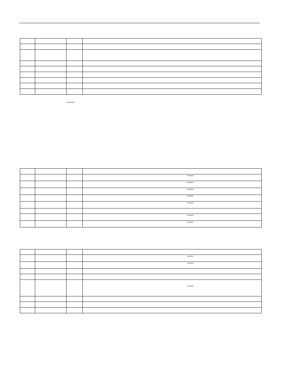
INTERRUPT INT STATUS REGISTER 2 (ADDRESS 0X42; POWER-UP
DEFAULT=00h) Table 10.4
BIT
NAME
R/W
DESCRIPTION
0
+12V_Error
R
A 1 indicates a High or Low limit has been exceeded.
1
-12V/
V
CCP2
_Error
R
A 1 indicates a High or Low limit has been exceeded.
2
Reserved
R
0
3
Reserved
R
0
4
Chassis_Error
R
A 1 indicates Chassis Intrusion has gone high.
5
Reserved
R
0
6
Reserved
R
0
7
Reserved
R
0
Note: Anytime the
INT
Status Registers are read out, the conditions (i.e., Registers) that are read are
automatically reset to power-up state (except CHS, which can only be cleared by CHS reset). In the case
of the VOLTAGE priority indication, if two or more voltages were out of LIMITS, then another
indication would automatically be generated if it were not handled during the ISR.
The errant voltage may be masked until the operator has time to clear the errant condition or set the limit
higher/lower.
INT MASK REGISTER 1 (ADDRESS 0X43; POWER-UP DEFAULT=00h)
Table 10.5
BIT
NAME
R/W
DESCRIPTION
0
+2.5V
R/W
A 1 disables the corresponding interrupt status bit for
INT
interrupt.
1
+V
CCP1
R/W
A 1 disables the corresponding interrupt status bit for
INT
interrupt.
2
+3.3V
R/W
A 1 disables the corresponding interrupt status bit for
INT
interrupt.
3
+5V
R/W
A 1 disables the corresponding interrupt status bit for
INT
interrupt.
4
Temp
R/W
A 1 disables the corresponding interrupt status bit for
INT
interrupt.
5
Reserved
R/W
Power on default = 0.
6
FAN1
R/W
A 1 disables the corresponding interrupt status bit for
INT
interrupt.
7
FAN2
R/W
A 1 disables the corresponding interrupt status bit for
INT
interrupt.
INT MASK REGISTER 2 (ADDRESS 0X44; POWER-UP DEFAULT=00h)
Table 10.6
BIT
NAME
R/W
DESCRIPTION
0
+12V
R/W
A 1 disables the corresponding interrupt status bit for
INT
interrupt.
1
-12V/V
CCP2
R/W
A 1 disables the corresponding interrupt status bit for
INT
interrupt.
2
Reserved
R/W
Power-up Default = 0.
3
Reserved
R/W
Power-up Default = 0.
4
CHS_sec
(Chassis
Intrusion)
R/W
A 1 disables the corresponding interrupt status bit for
INT
interrupt.
5
Reserved
R/W
Power-up Default = 0.
6
Reserved
R/W
Power-up Default = 0.
7
Reset Enable
R/W
A 1 enables the RESET in the configuration register.