Figure 2. state diagram, Reset, Presence test – Rainbow Electronics DS2715 User Manual
Page 6: Prechg, Fault, Fast charge, Topoff charge, Done, Ds2715 state diagram discharge mode
DS2715: NiMH Cell Pack Charge Controller
6 of 12
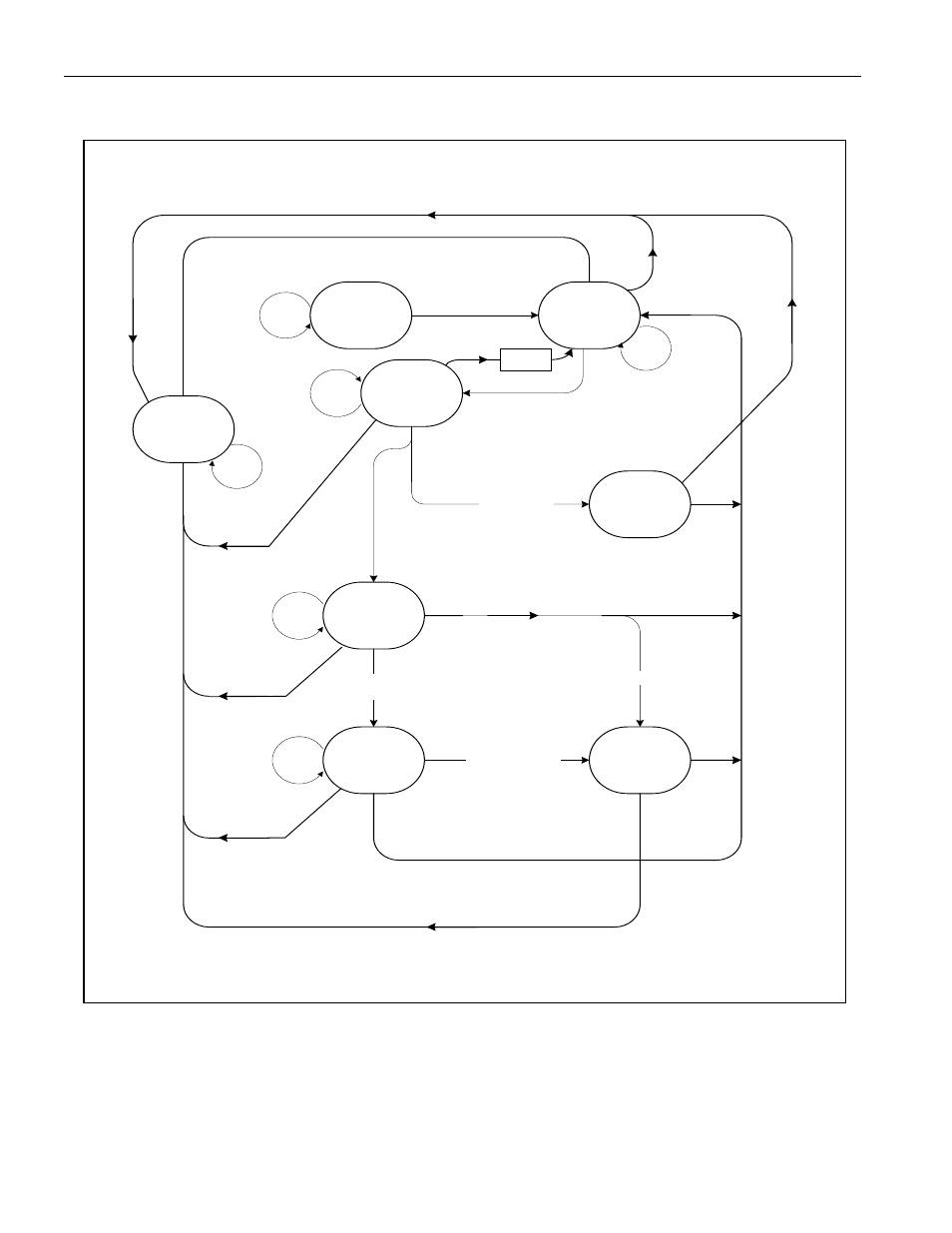
Figure 2. STATE DIAGRAM
Reset
Standby power
Check Rt, set mode
Vch = Hi-Z
LEDx = Hi-Z
V
DD
> V
UVLO
Presence
TEST
Vch = Hi-Z
LED Hi-Z= No Battery
t < PCTimeout
AND
Vbatt < 1V
V
DD
< V
UVLO
-V
UVLO-HYS
(asynchronously from
anywhere)
PreCHG
Vref = 0.033V
LED1 = Charging
30 min PCtimeout
FAULT
Vch = Hi-Z
LED2 = Fault
Flash until Vbatt>1.65
T > 50
Fast
CHARGE
Vref = 0.121V
LED1 = Charging
t < Fast Timeout
Topoff
CHARGE
Vref= 0033V
LED1 = Charging
t < Topoff Timeout
dT/dt OR
t > Fast Timeout
DONE
Vch = Hi-Z
LED2 = DONE
T > 50
OR
t > Topoff Timeout
t > PCTimeout
OR
T > 50
Vbatt > 1.65
Vbatt>1.65
Vbatt > 1.65V
OR
T < 0C
OR
T > 45C
Vbatt > 1.65
or
Vbatt < 1.0
Vbatt > 1.65
Overtemp, Overvoltage Detect
DS2715 State Diagram
Discharge
Mode
Pwr=Low
LEDs = OFF
Vch = LOW
Vbatt>1V
AND
T < PCTimeout
AND
T < 50C
Discharge
Latch
Still Set?
Latch
Reset
Discharge latch set
Discharge latch set
Di
sc
ha
rg
e
La
tc
h
se
t
Discharge latch set
Vbatt < 1.55V
AND
0C < T < 45C
4 Sec
Delay
Di
sc
ha
rg
e
lat
ch
se
t
Discharge
Latch Set