Rainbow Electronics DS1486P User Manual
Features, Ordering information, Pin description
1 of 17
072401
FEATURES
§ 128 kbytes of user NV RAM
§ Integrated NV SRAM, real-time clock,
crystal, power-fail control circuit and lithium
energy source
§ Totally nonvolatile with over 10 years of
operation in the absence of power
§ Watchdog timer restarts an out-of-control
processor
§ Alarm function schedules real-time related
activities such as system wakeup
§ Programmable interrupts and square wave
output
§ All registers are individually addressable via
the address and data bus
§ Interrupt signals active in power-down mode
ORDERING INFORMATION
DS1486
XXX
(32–pin DIP module)
–150
150 ns access
–120
120 ns access
*DS1486P
XXX
34-pin PowerCap Module Board
–150
150 ns access
–120
120 ns access
*DS9034PCX PowerCap Required
(must be ordered separately)
PIN DESCRIPTION
INTB
– Interrupt Output A (open drain)
INTB
(INTB) – Interrupt Output B (open drain)
A0–A16 –
Address
Inputs
DQ0–DQ7 –
Data
Input/Output
CE
– Chip Enable
OE
– Output Enable
WE
– Write Enable
V
CC
– +5 Volts
GND –
Ground
SQW
– Square Wave Output
NC
– No Connection
X1, X2
– Crystal Connection
V
BAT
– Battery Connection
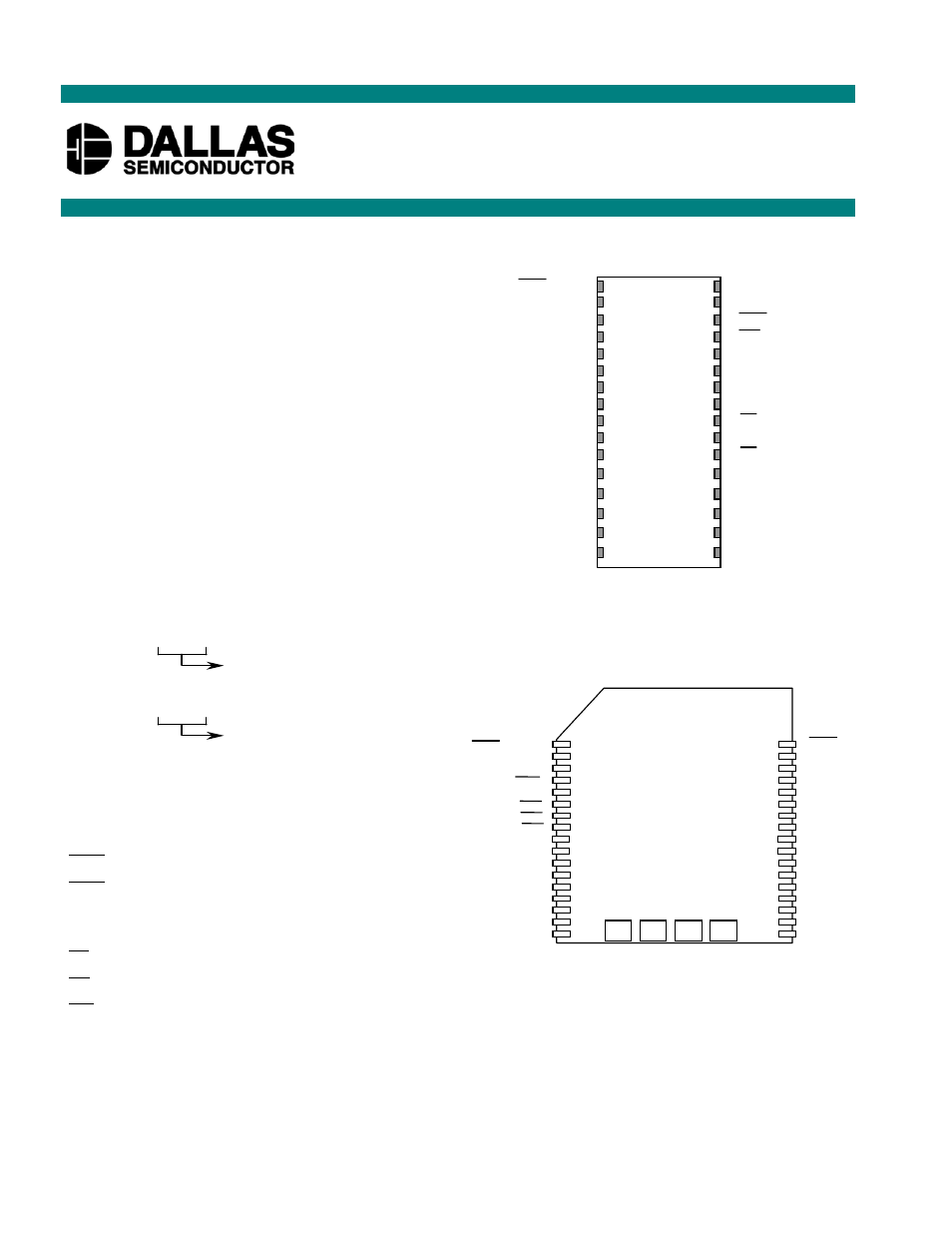
PIN ASSIGNMENT
DS1486/DS1486P
RAMified Watchdog Timekeeper
www.maxim-ic.com
34
1
INTB (INTB)
2
3
A15
A16
PFO
V
CC
WE
OE
CE
DQ7
DQ6
DQ5
DQ4
DQ3
DQ2
DQ1
DQ0
GND
4
5
6
7
8
9
10
11
12
13
14
15
16
17
SQW
A14
33
32
31
30
29
28
27
26
25
24
23
22
21
20
19
18
A13
A12
A11
A10
A9
A8
A7
A6
A5
A4
A3
A2
A1
A0
INTA
X1 GND V
BAT
X2
34-Pin PowerCap Module Board
(Uses DS9034PCX PowerCap)
INTB (INTB)
13
1
2
3
4
5
6
7
8
9
10
11
12
14
31
DS1486 128k x 8
32-Pin Encapsulated Package
A14
A7
A5
A4
A3
A2
A1
A0
DQ1
DQ0
V
CC
A15
INTA/SQW
WE
A13
A8
A9
A11
OE
A10
CE
DQ7
DQ5
DQ6
32
30
29
28
27
26
25
24
23
22
21
19
20
A16
A12
A6
DQ2
GND
15
16
18
17
DQ4
DQ3