Ds2741, Detailed description – Rainbow Electronics DS2741 User Manual
Page 6
DS2741
Detailed Description
The DS2741 is a small, low-cost, current-sensing and
accumulation IC that is intended for current-monitoring
applications. The differential voltage measured across
the on-chip 38m
Ω sense resistor is digitized by an
internal ADC that provides an accurately scaled digital
signed 10-bit value that represents bidirectional current
up to
±2.5A. The measured current result is reported in
an internal SRAM register that can be read using the
I
2
C interface. After each current measurement, the
signed result value is added to an accumulator in order
to maintain a signed accumulated current value with a
0.247mAhr LSB and a full-scale range of
±8.1Ahrs. The
device can be placed into a low-power sleep mode
when current measurements are not needed.
Power Modes
The DS2741 has two power modes: active and sleep.
While in active mode, the DS2741 continually measures
and accumulates current and provides data to the host
system through its I
2
C interface. In sleep mode, the
DS2741 ceases these activities. The DS2741 enters
sleep mode whenever an active-low signal is applied to
the SLP pin and remains in sleep as long as the SLP
pin is held low. Active mode resumes when the SLP pin
is returned to a logic-high level. The SLP pin resets the
Current and Temperature registers, but not the Current
Accumulator register.
Current Measurement
In active mode, the DS2741 continually measures the cur-
rent flow into and out of the battery by measuring the volt-
age drop across the internally integrated 38m
Ω
current-sense resistor. The DS2741 considers the voltage
difference between pins RS+ and RS- (V
RS
= V
RS+
- V
RS-
)
to be the filtered voltage drop across the sense resis-
tor. A positive V
RS
value indicates current is flowing into
the battery (charging), while a negative V
RS
value indi-
cates current is flowing out of the battery (discharging).
V
RS
is measured with a signed resolution of 10 bits.
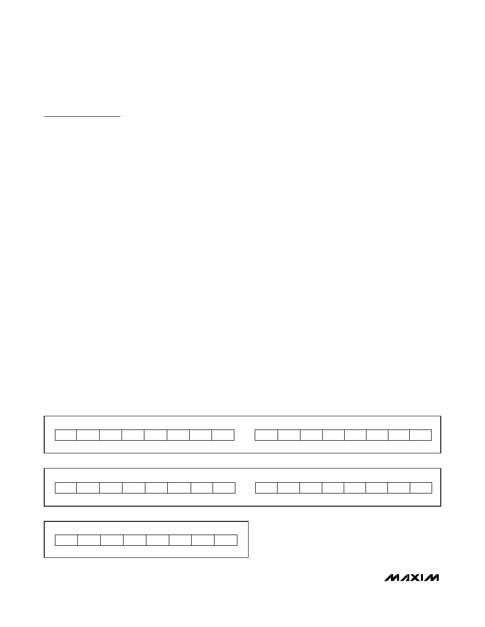
The current register is updated in two’s-complement
format every 22.7ms with an average of eight readings.
Current measurements outside the register range are
reported at the range limit. Figure 1 shows the format of
the current register.
The DS2741 maintains the current register in units of
amps, with a resolution of 2.64mA and full-scale range
of no less than
±2.5A. The DS2741 automatically com-
pensates for internal sense resistor process variations
and temperature effects when reporting current.
Current Accumulator
The current accumulator facilitates remaining capacity
estimation by tracking the net current flow into and out of
the battery. Current flow into the battery increments the
current accumulator, while current flow out of the battery
decrements it. The DS2741 maintains the current accu-
mulator 0.247mAhrs resolution and full-scale value of
±8.1Ahrs range. Data is maintained in the current accu-
mulator in two’s-complement format. Figure 2 shows the
format of the current accumulator. The current accumu-
lator is a read/write register that can be altered by the
host system as needed. The Current Accumulator regis-
ter is not reset when the DS2741 is in sleep mode.
Temperature Measurement
The on-board temperature sensor measures tempera-
tures from +127°C to -128°C. The LSb of register 14h
has a 1°C bit weight. See Figure 3 for the temperature
register’s two’s-complement format.
Current Monitor and Accumulator with
Integrated Sense Resistor
6
_______________________________________________________________________________________
MSB—ADDRESS 16h
LSB—ADDRESS 17h
S
2
9
2
8
2
7
2
6
2
5
2
4
2
3
2
2
2
1
2
0
X
X
X
X
X
MSb
LSb
MSb
LSb
Figure 1. Current Register Format
MSB—ADDRESS 10h
LSB—ADDRESS 11h
S
2
14
2
13
2
12
2
11
2
10
2
9
2
8
2
7
2
6
2
5
2
4
2
3
2
2
2
1
2
0
MSb
LSb
MSb
LSb
Figure 2. Current Accumulator Register Format
ADDRESS 14h
S
2
6
2
5
2
4
2
3
2
2
2
1
2
0
MSb
LSb
Figure 3. Temperature Register Format