Pin description, Block diagram – Rainbow Electronics DS2741 User Manual
Page 5
DS2741
Current Monitor and Accumulator with
Integrated Sense Resistor
_______________________________________________________________________________________
5
Pin Description
PIN
NAME
FUNCTION
1–4 RS+
Sense Resistor High Side. Connection to high side of internal 38m
sense resistor. All RS+ pins
must be connected together.
5 SDA
Serial Data Input/Output. SDA is the input/output pin for the I
2
C serial interface. The SDA pin is an
open-drain output and requires an external pullup resistor.
6
SCL
Serial Clock Input. SCL is used to synchronize data movement on the I
2
C serial interface.
7 V
CC
Supply Voltage. Power-supply input.
8
DNC
Do Not Connect
9 GND
Ground
10
SLP
Sleep Input (Active Low). When taken low, the DS2741 is placed in a low-power sleep state where
all internal circuitry including the I
2
C bus is disabled. Toggling the
SLP pin low and then back high
resets the device and the I
2
C bus logic.
11–14 RS-
Sense Resistor Low Side. Connection to low side of internal 38m
sense resistor. All RS- pins
must be connected together.
—
EP
Exposed Pad. Can be left floating.
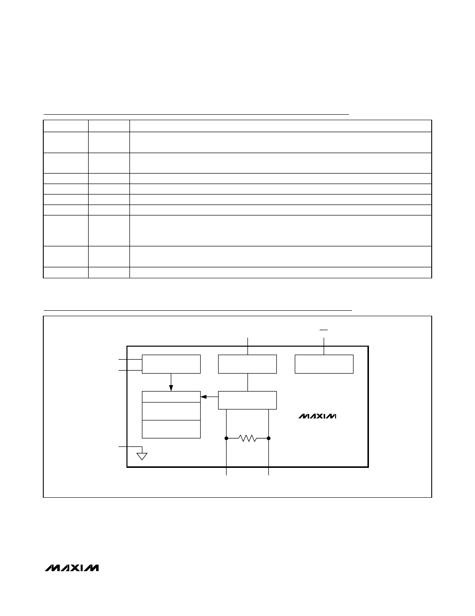
Block Diagram
38m
Ω
I
2
C
INTERFACE
VOLTAGE
REFERENCE
10-BIT PLUS SIGN
A/D CONVERTER
POWER
CONTOL
CURRENT ACCUMULATOR
REGISTER
TEMPERATURE
REGISTER
CURRENT REGISTER
SDA
V
CC
RS+
RS-
SLP
SCL
GND
DS2741