Rainbow Electronics ICL7665 User Manual
Page 7
Basic Over/Undervoltage
Detection Circuits
Figures 3, 4, and 5 show the three basic voltage detec-
tion circuits.
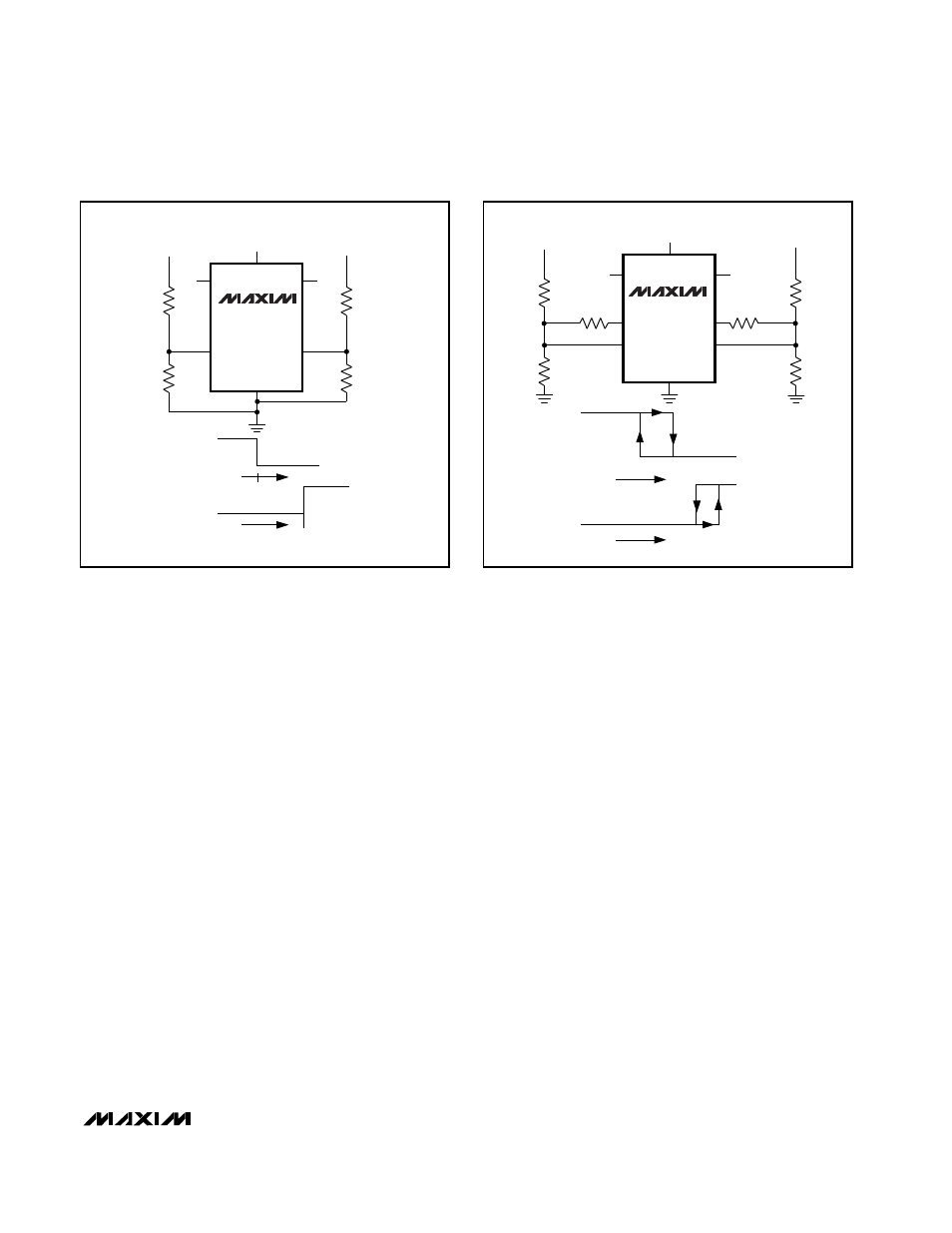
The simplest circuit, depicted in Figure 3, does not
have any hysteresis. The comparator trip-point formulas
can easily be derived by observing that the comparator
changes state when the V
SET
input is 1.3V. The exter-
nal resistors form a voltage divider that attenuates the
input signal. This ensures that the V
SET
terminal is at
1.3V when the input voltage is at the desired compara-
tor trip point. Since the bias current of the comparator
is only a fraction of a nanoamp, the current in the volt-
age divider can be less than one microamp without los-
ing accuracy due to bias currents. The ICL7665A has a
2% threshold accuracy at +25°C, and a typical temper-
ature coefficient of 100ppm/°C including comparator
offset drift, eliminating the need for external poten-
tiometers in most applications.
Figure 4 adds another resistor to each voltage detector.
This third resistor supplies current from the HYST out-
put whenever the V
SET
input is above the 1.3V thresh-
old. As the formulas show, this hysteresis resistor
affects only the lower trip point. Hysteresis (defined as
the difference between the upper and lower trip points)
keeps noise or small variations in the input signal from
repeatedly switching the output when the input signal
remains near the trip point for a long period of time.
The third basic circuit, Figure 5, is suitable only when the
voltage to be detected is also the power-supply voltage for
the ICL7665. This circuit has the advantage that all of the
current flowing through the input divider resistors flows
through the hysteresis resistor. This allows the use of
higher-value resistors, without hysteresis output leakage
having an appreciable effect on the trip point.
Resistor-Value Calculations
Figure 3
1) Choose a value for R11. This value determines the
amount of current flowing though the input divider,
equal to V
SET
/ R11. R11 can typically be in the
range of 10k
Ω
to 10M
Ω
.
2) Calculate R21 based on R11 and the desired trip
point:
V
TRIP
– V
SET
V
TRIP
– 1.3V
R21 = R11
(
———————
)
= R11
(
——————
)
V
SET
1.3V
ICL7665
Microprocessor Voltage Monitor with
Dual Over/Undervoltage Detection
_______________________________________________________________________________________
7
Figure 3. Simple Threshold Detector
Figure 4. Threshold Detector with Hysteresis
ICL7665
OUT1
OUT2
SET2
SET1
R21
R11
R22
R12
V
IN1
V+
V
IN2
OUT1
V
IN1
V
TRIP1
V
TRIP2
OUT2
V
IN2
ICL7665
OUT1
OUT2
SET2
SET1
R21
R11
R22
R12
V
IN1
V+
V
IN2
HYST1
HYST2
R31
R32
V+
OUT1
V
L1
V
U1
0V
V+
V
U2
OUT2
V
IN1
0V
V
L2
V
IN2