Rainbow Electronics DS3904 User Manual
Page 9
DS3904
DS3904 Triple 128-Position Nonvolatile
Variable Digital Resistor/Switch
_____________________________________________________________________
9
Data Valid:
The state of the data line represents valid
data when, after a start condition, the data line is stable
for the duration of the high period of the clock signal. The
data on the line can be changed during the low period of
the clock signal. There is one clock pulse per bit of data.
Figures 2 and 3 detail how data transfer is accomplished
on the 2-wire bus. Depending upon the state of the R/W
bit, two types of data transfer are possible.
Each data transfer is initiated with a start condition and
terminated with a stop condition. The number of data
bytes transferred between start and stop conditions is
not limited and is determined by the master device. The
information is transferred byte-wise and each receiver
acknowledges with a ninth bit.
Within the bus specifications, a regular mode (100kHz
clock rate) and a fast mode (400kHz clock rate) are
defined. The DS3904 works in both modes.
Acknowledge:
Each receiving device, when
addressed, generates an acknowledge after the byte
has been received. The master device must generate
an extra clock pulse that is associated with this
acknowledge bit.
A device that acknowledges must pull down the SDA
line during the acknowledge clock pulse in such a way
that the SDA line is a stable low during the high period
of the acknowledge-related clock pulse. Of course,
setup and hold times must be taken into account. A
STOP
CONDITION
OR REPEATED
START
CONDITION
REPEATED IF MORE BYTES
ARE TRANSFERRED
ACK
START
CONDITION
ACK
ACKNOWLEDGEMENT
SIGNAL FROM RECEIVER
ACKNOWLEDGEMENT
SIGNAL FROM RECEIVER
SLAVE ADDRESS
MSB
SCL
SDA
R/W
DIRECTION
BIT
1
2
6
7
8
9
1
2
8
9
3–7
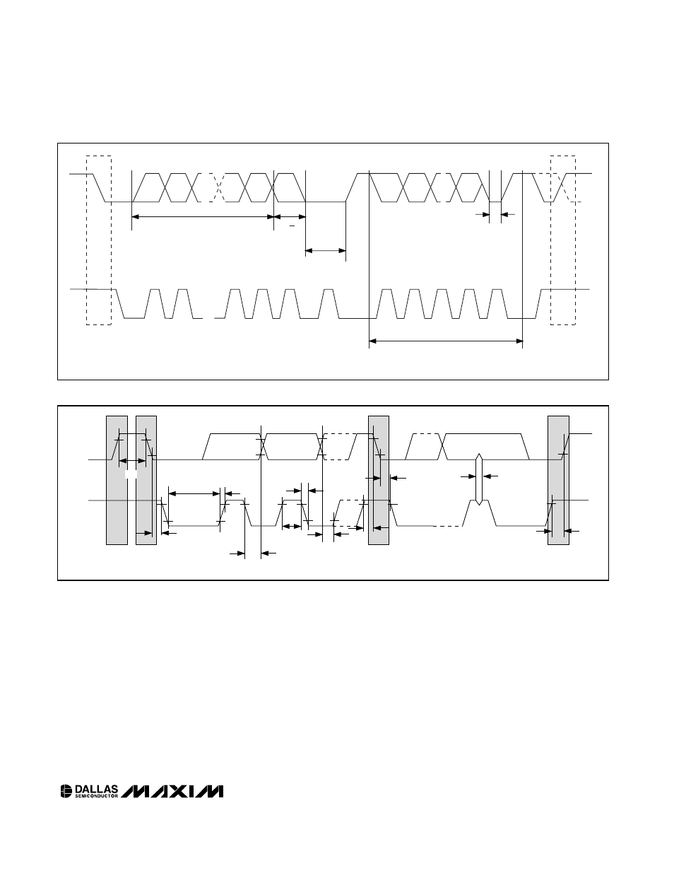
Figure 2. 2-Wire Data Transfer Protocol
SDA
SCL
t
HD:STA
t
LOW
t
HIGH
t
R
t
F
t
HD:DAT
t
SU:DAT
REPEATED
START
t
SU:STA
t
HD:STA
t
SU:STO
t
SP
STOP
START
t
BUF
Figure 3. 2-Wire AC Characteristics