Setting the clock, Stopping and starting the clock oscillator, Frequency test bit – Rainbow Electronics DS1644P User Manual
Page 3
DS1644/DS1644P
3 of 11
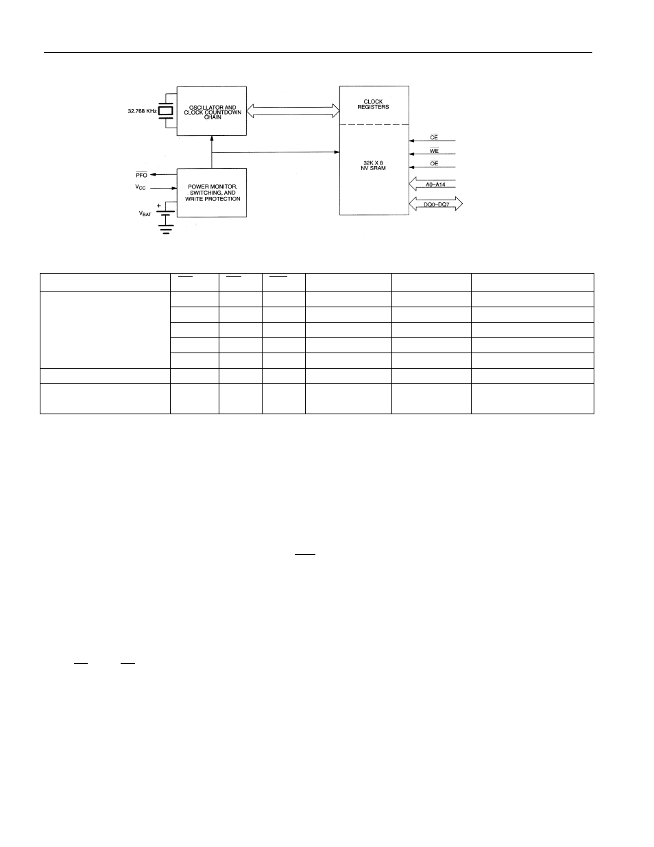
DS1644 BLOCK DIAGRAM Figure 1
DS1644 TRUTH TABLE Table 1
V
CC
CE
OE
WE
MODE
DQ
POWER
V
IH
X
X
DESELECT
HIGH-Z
STANDBY
X
X
X
DESELECT
HIGH-Z
STANDBY
V
IL
X
V
IL
WRITE
DATA IN
ACTIVE
V
IL
V
IL
V
IH
READ
DATA OUT
ACTIVE
5V
±
10%
V
IL
V
IH
V
IH
READ
HIGH-Z
ACTIVE
<4.5V >V
BAT
X
X
X
DESELECT
HIGH-Z
CMOS STANDBY
BAT X X X DESELECT HIGH-Z DATA RETENTION SETTING THE CLOCK The MSB Bit, (B7) of the control register is the write bit. Setting the write bit to a 1, like the read bit, STOPPING AND STARTING THE CLOCK OSCILLATOR The clock oscillator may be stopped at any time. To increase the shelf life, the oscillator can be turned off to minimize current drain from the battery. The OSC bit is the MSB for the seconds registers. Setting it to a 1 stops the oscillator. FREQUENCY TEST BIT Bit 6 of the day byte is the frequency test bit. When the frequency test bit is set to logic 1 and the (i.e., CE low, OE low, and address for seconds register remain valid and stable).
MODE
halts updates to the DS1644 registers. The user can then load them with the correct day, date and time
data in 24-hour BCD format. Resetting the write bit to a 0 then transfers those values to the actual clock
counters and allows normal operation to resume.
oscillator is running, the LSB of the seconds register will toggle at 512 Hz. When the seconds register is
being read, the DQ0 line will toggle at the 512 Hz frequency as long as conditions for access remain valid