I/o ports, 1 port configuration – Rainbow Electronics AT89LP214 User Manual
Page 22
22
3538A–MICRO–7/06
AT89LP213/214 [Preliminary]
13. I/O Ports
The AT89LP213/214 can be configured for between 9 and 12 I/O pins. The exact number of I/O
pins available depends on the clock and reset options as shown in
. All port pins are
5V tolerant, that is they can be pulled up or driven to 5.5V even when operating at a lower V
CC
such as 3V.
13.1
Port Configuration
All port pins on the AT89LP213/214 may be configured to one of four modes: quasi-bidirectional
(standard 8051 port outputs), push-pull output, open-drain output, or input-only. Port modes may
be assigned in software on a pin-by-pin basis as shown in
. The Tristate-Port User
Fuse determines the default state of the port pins. When the fuse is enabled, all port pins default
to input-only mode after reset. When the fuse is disabled, all port pins, with the exception of P1.0
and P1.1, default to quasi-bidirectional mode after reset and are weakly pulled high. Each port
pin also has a Schmitt-triggered input for improved input noise rejection. During Power-down all
the Schmitt-triggered inputs are disabled with the exception of P1.3, P3.2 and P3.3, which may
be used to wake up the device. Therefore P1.3, P3.2 and P3.3 should not be left floating during
Power-down
Table 12-4.
IPH
– Interrupt Priority High Register
IPH = B7H
Reset Value = X000 0000B
Not Bit Addressable
–
–
PGH
PSH
PT1H
PX1H
PT0H
PX0H
Bit
7
6
5
4
3
2
1
0
Symbol
Function
PGH
General-purpose Interrupt Priority High
PSH
Serial Port Interrupt Priority High
PT1H
Timer 1 Interrupt Priority High
PX1H
External Interrupt 1 Priority High
PT0H
Timer 0 Interrupt Priority High
PX0H
External Interrupt 0 Priority High
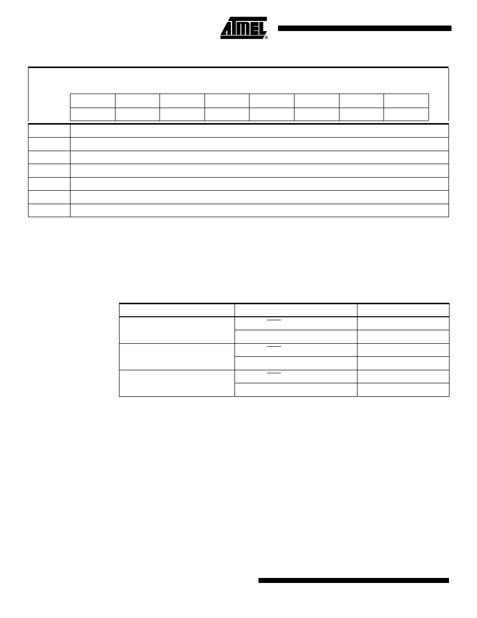
Table 13-1.
I/O Pin Configurations
Clock Source
Reset Option
Number of I/O Pins
External Crystal or Resonator
External RST Pin
9
No external reset
10
External Clock
External RST Pin
10
No external reset
11
Internal RC Oscillator
External RST Pin
11
No external reset
12