Rainbow Electronics AT89LP214 User Manual
Page 14
14
3538A–MICRO–7/06
AT89LP213/214 [Preliminary]
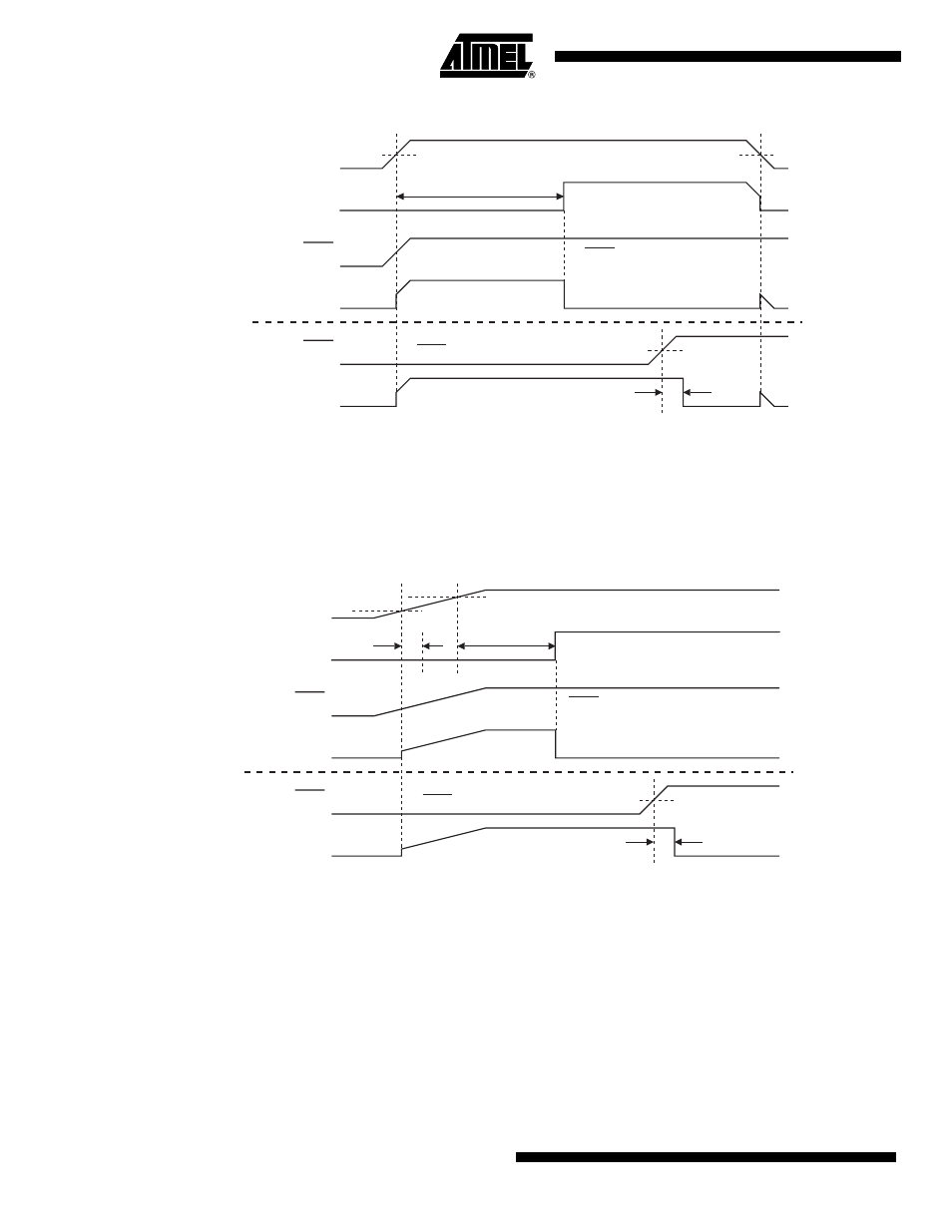
Figure 10-1. Power-on Reset Sequence (BOD Disabled)
If the Brown-out Detector (BOD) is also enabled, the start-up timer does not begin counting until
after V
CC
reaches the BOD threshold voltage V
BOD
as shown in
. However, if this
event occurs prior to the end of the initialization sequence, the timer must first wait for that
sequence to complete before counting.
Figure 10-2. Power-on Reset Sequence (BOD Enabled)
Note:
t
POR
is approximately 92 µs ± 5%.
The start-up timer delay is user configurable with the Start-up Time User Fuses and depends on
the clock source (
). The start-up delay should be selected to provide enough settling
time for V
CC
and the selected clock source. The Start-Up Time fuses also control the length of
the start-up time after a Brown-out Reset or when waking up from Power-down during internally
timed mode.
V
CC
RST
TIME-OUT
t
POR
+ t
SUT
t
RHD
V
POR
INTERNAL
RESET
RST
INTERNAL
RESET
V
RH
(RST Tied to V
CC
)
(RST Controlled Externally)
V
POR
V
CC
RST
TIME-OUT
t
POR
t
RHD
V
POR
INTERNAL
RESET
RST
INTERNAL
RESET
V
RH
t
SUT
V
BOD
(RST Tied to V
CC
)
(RST Controlled Externally)