Ds1866 ordering information – Rainbow Electronics DS1866 User Manual
Page 5
DS1866
5 of 5
102199
NOTES:
1. All voltages are referenced to ground.
2. For V
CC
= 5V ± 10% maximum V
IL
= +0.8V. For V
CC
3.0 ± 10% V
IL
= +0.6V. For V
CC
=2.7 volts V
IH
=2.0 volts minimum.
3. Resistor input voltages cannot go below ground or exceed V
CC
by the amounts as shown in the table.
4. Maximum current specifications are based on the change rate of the parallel port inputs P0, P1, and
P2.
5. Standby current specifications apply when P0, P1, P2 logic inputs are driven within the specified V
IH
or V
IL
levels.
6. Valid at 25
°C only.
7. The end-to-end resistance tolerance of the DS1866 can be expected to shift with temperature.
However, this change will not exceed ±20% of the nominal resistor value of the part.
8. Absolute tolerance is used to compare measured wiper voltage versus expected wiper voltage as
determined by wiper position. The DS1866 is specified to provide an absolute tolerance of ±1.0 dB.
9. Tap-to-tap tolerance is used to determine the change in voltage between successive tap positions. The
DS1866 is specified to provide a tap-to-tap tolerance specification of ±1.0 dB.
10. -3 dB cutoff frequency characteristic for the DS1866 is 1 MHz.
11. Capacitance values apply at 25°C.
12. This specification refers to the time difference between parallel port input changes to stabilize a wiper
transition.
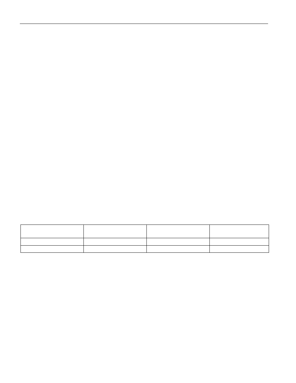
DS1866 ORDERING INFORMATION
ORDERING NUMBER
PACKAGE
OPERATING
TEMPERATURE
VERSION
DS1866
8L DIP
-40°C TO +85°C
10k
Ω
DS1866Z
8L SOIC (150-MIL)
-40°C TO +85°C
10k
Ω