Ds7505, Digital thermometer and thermostat – Rainbow Electronics DS7505 User Manual
Page 12
DS7505
Copy Data [48h]
0100 1000
Copies data from all SRAM shadow registers to
EEPROM. It is recommended that a Copy Data com-
mand be performed after writing EEPROM-backed
memory locations to guarantee data integrity in the
event of a power loss. The master sends a START fol-
lowed by an address byte containing the DS7505 bus
address. The R/W bit must be a 0. The DS7505
responds with an ACK. If the next byte is a 0x48, the
DS7505 copies all Shadow RAM locations in EEPROM
memory.
Software POR [54h]
0101 0100
The master sends a START followed by an address
byte containing the DS7505 bus address. The R/W bit
must be a 0. The DS7505 responds with an ACK. If the
next byte is a 0x54, the DS7505 resets as if power had
been cycled, which stops temperature conversions and
resets all registers to their power-up states. No ACK is
sent by the IC after the POR command is received.
Afterwards, the DS7505 makes a single temperature
conversion or continuous temperature conversions,
depending on the state of the SD bit.
Digital Thermometer and Thermostat
12
______________________________________________________________________________________
SCL
START
ADDRESS BYTE
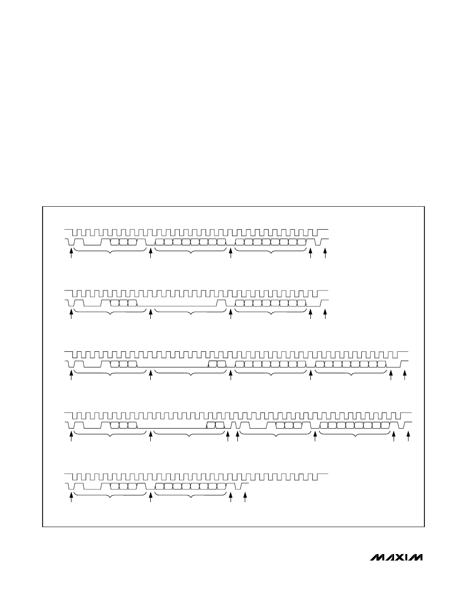
A) READ 2 BYTES FROM THE TEMPERATURE, T
OS
, OR T
HYST
REGISTER (CURRENT POINTER LOCATION)
SDA
S
1
0
0
1
A2 A1 A0
R
A
A
N
P
D7 D6 D5 D4 D3 D2 D1 D0
D7 D6 D5 D4 D3 D2 D1 D0
MS DATA BYTE
(FROM SLAVE)
LS DATA BYTE
(FROM SLAVE)
ACK
(SLAVE)
ACK
(MASTER)
NACK
(MASTER)
STOP
SCL
START
ADDRESS BYTE
E) READ FROM THE CONFIGURATION REGISTER (CURRENT POINTER LOCATION)
SDA
S
1
0
0
1
A2 A1 A0
R
A
N
P
D7 D6 D5 D4 D3 D2 D1 D0
MS DATA BYTE
(FROM SLAVE)
ACK
(SLAVE)
NACK
(MASTER)
STOP
SCL
START
ADDRESS BYTE
B) WRITE TO THE CONFIGURATION REGISTER
SDA
S
1
0
0
1
A2 A1 A0 W
A
A
A
P
0
0
0
0
0
0
0
1
D7 D6 D5 D4 D3 D2 D1 D0
POINTER BYTE
DATA BYTE
(FROM MASTER)
ACK
(SLAVE)
ACK
(SLAVE)
ACK
(SLAVE)
STOP
SCL
START
ADDRESS BYTE
C) WRITE TO THE T
OS
OR T
HYST
REGISTER
SDA
S
1
0
0
1
A2 A1 A0 W
A
A
0
0
0
0
0
0
P1 P0
D7 D6 D5 D4 D3 D2 D1 D0
POINTER BYTE
MS DATA BYTE
(FROM MASTER)
ACK
(SLAVE)
ACK
(SLAVE)
A
A
P
D7 D6 D5 D4 D3 D2 D1
LS DATA BYTE
(FROM MASTER)
ACK
(SLAVE)
ACK
(SLAVE)
STOP
SCL
START
ADDRESS BYTE
D) READ SINGLE BYTE (NEW POINTER LOCATION)
SDA
S
1
0
0
1
A2 A1 A0 W
A
A
S
0
0
0
0
0
0
P1 P0
1
0
0
1
A2 A1 A0
POINTER BYTE
ADDRESS BYTE
ACK
(SLAVE)
ACK
(SLAVE)
REPEAT
START
R
A
N
P
D7 D6 D5 D4 D3 D2 D1 D0
DATA BYTE
(FROM SLAVE)
ACK
(SLAVE)
NACK
(MASTER)
STOP
Figure 9. 2-Wire Interface Timing