Rainbow Electronics BA15218N User Manual
Page 4
4
Standaed ICs
BA15218 / BA15218F / BA15218N
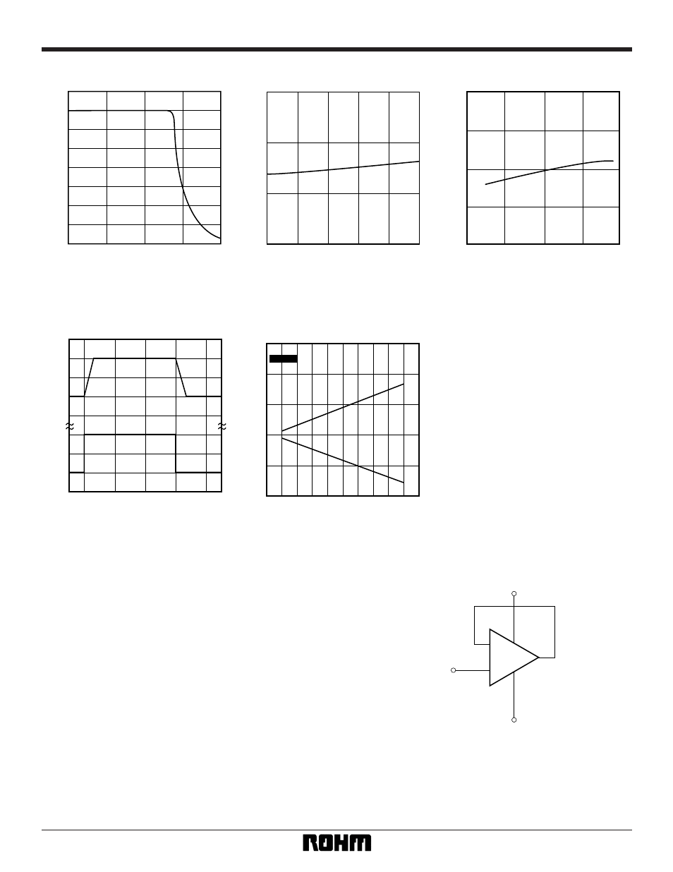
MAXIMUM OUTPUT VOLTAGE: V
OM
(V)
FREQUENCY: f (Hz)
32
4
8
12
16
20
24
28
0
100
1k
10k
100k
1M
Fig.4 Maximum output voltage vs.
frequency
INPUT BIAS CURRENT: I
B
(nA)
AMBIENT TEMPERATURE: Ta (
°
C)
20
40
60
80
– 20
0
20
40
60
80
Fig.5 Input bias current vs.
ambient temperature
INPUT BIAS CURRENT: I
B
(nA)
POWER SUPPLY VOLTAGE: V
+
(V)
10
100
75
50
25
20
30
0
40
Fig.6 Input bias current vs.
power supply voltage
INPUT VOLTAGE OUTPUT VOLTAGE
V
IN
(V) V
OUT
(V)
TIME (
µ
s)
0
– 5
5
– 5
5
0
20
30
40
10
0
Fig.7 Output response characteristics
MAXIMUM OUTPUT VOLTAGE: V
OM
(V)
POWER SUPPLY VOLTAGE: V
±
(V)
30
– 20
– 10
0
10
20
0
±
10
±
20
R
L
= 2k
Ω
Fig.8 Maximum output voltage vs.
power supply voltage
•
Operation notes
(1) Unused circuit connections
If there are any circuits which are not being used, we
recommend making connections as shown in Figure 9,
with the non-inverted input pin connected to the poten-
tial within the in-phase input voltage range (V
ICM
).
V
CC
V
EE
+
–
To potential
in V
ICM
Fig.9 Unused circuit connections
- MAX9758 (31 pages)
- MAX9729 (28 pages)
- MAX4074_MAX4078 (20 pages)
- MAX98300 (1 page)
- MAX9730 (14 pages)
- MAX9618 (10 pages)
- MAX9945 (13 pages)
- MAX9717 (19 pages)
- MAX9203 (8 pages)
- MAX9109 (10 pages)
- MAX9034 (11 pages)
- MAX98302 (13 pages)
- MAX4249_MAX4257 (19 pages)
- MAX9770 (24 pages)
- MAX9741 (1 page)
- MAX98314 (14 pages)
- MAX9792 (30 pages)
- MAX44252 (15 pages)
- MAX9077 (8 pages)
- MAX4029 (13 pages)
- MAX9700 (19 pages)
- MAX9634 (11 pages)
- MAX9714 (18 pages)
- MAX98500 (15 pages)
- MAX9712 (18 pages)
- MAX9755 (31 pages)
- MAX4198_MAX4199 (12 pages)
- MAX9920 (18 pages)
- MAX4244 (16 pages)
- MAX4165_MAX4169 (16 pages)
- MAX9796 (27 pages)
- MAX9768 (25 pages)
- MAX4284 (20 pages)
- MAX4039 (18 pages)
- MAX9944 (15 pages)
- MAX9610 (11 pages)
- MAX9814 (14 pages)
- MAX9820 (13 pages)
- MAX9693 (10 pages)
- MAX9938 (9 pages)
- MAX4334 (16 pages)
- MAX4329 (12 pages)
- MAX4163 (14 pages)
- MXL1116 (4 pages)
- MAX9013 (12 pages)