Phantom clock register information, Figure 2. phantom clock protocol defintion – Rainbow Electronics DS1254 User Manual
Page 4
DS1254
4 of 17
advance and all subsequent write cycles are ignored. If a read cycle occurs at any time during pattern
recognition, the present sequence is aborted and the comparison register pointer is reset. Pattern
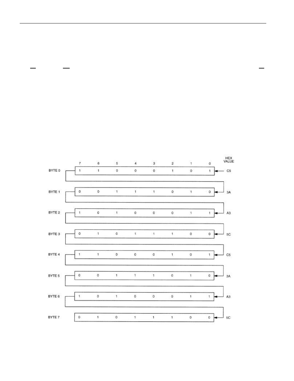
recognition continues for a total of 64 write cycles as described above until all the bits in the comparison
register have been matched (this bit pattern is shown in Figure 2). With a correct match for 64-bits, the
phantom clock is enabled and data transfer to or from the timekeeping registers can proceed. The next 64
cycles will cause the phantom clock to either receive or transmit data on DQ0, depending on the level of
the
OE
pin or the
WE
pin. Cycles to other locations outside the memory block can be interleaved with
CE
cycles without interrupting the pattern recognition sequence or data transfer sequence to the phantom
clock.
PHANTOM CLOCK REGISTER INFORMATION
The phantom clock information is contained in eight registers of 8 bits, each of which is sequentially
accessed one bit at a time after the 64-bit pattern recognition sequence has been completed. When
updating the phantom clock registers, each register must be handled in groups of 8 bits. Writing and
reading individual bits within a register could produce erroneous results. These read/write registers are
defined in Figure 3.
Figure 2. PHANTOM CLOCK PROTOCOL DEFINTION
Note: The pattern recognition in Hex is C5, 3A, A3, 5C, C5, 3A, A3, 5C. The odds of this pattern being
accidentally duplicated and causing inadvertent entry to the phantom clock is less than 1 in 10
19
. This
pattern is sent to the phantom clock LSB to MSB.