Pin description – Rainbow Electronics DS1087L User Manual
Page 7
DS1087L
3.3V Spread-Spectrum EconOscillator
_____________________________________________________________________
7
Pin Description
PIN
NAME
FUNCTION
1
OUT
Oscillator Output
2
SPRD
Dither Enable. When the pin is high, the dither is enabled. When the pin is low, the dither is disabled.
3
V
CC
Power Supply
4
GND
Ground
5
OE
Output Enable. When the pin is high, the output buffer is enabled. When the pin is low, the output is
disabled but the internal master oscillator is still on.
6
PDN
Power-Down. When the pin is high, the master oscillator is enabled. When the pin is low, the master
oscillator is disabled (power-down mode).
7
SDA
2-Wire Serial Data. This pin is for serial data transfer to and from the device.
8
SCL
2-Wire Serial Clock. This pin is used to clock data into and out of the device.
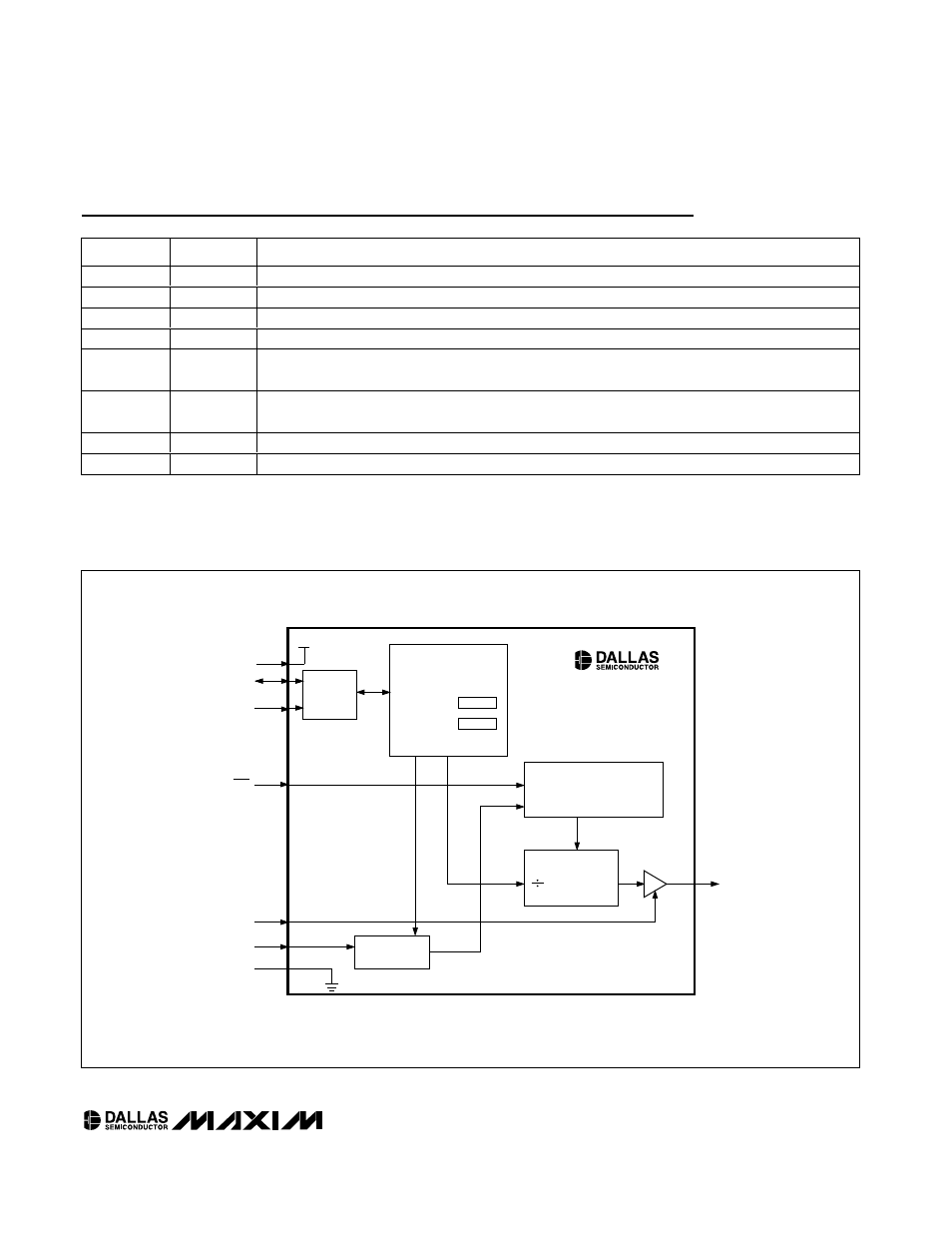
Figure 1. Functional Diagram
SDA
SCL
2-WIRE
INTERFACE
V
CC
EEPROM CONTROL
REGISTERS
PRESCALER
ADDR
SPRD
PDN
OUT
OE
TRIANGLE WAVE
GENERATOR
FACTORY-PROGRAMMED
OSCILLATOR
PRESCALER
BY 1, 2, 4...256
GND
MASTER
OSCILLATOR
OUTPUT
DITHER SIGNAL
DITHER
CONTROL
DS1087L