Pin description – Rainbow Electronics MAX5943 User Manual
Page 9
MAX5943
FireWire Current Limiter and Low-Drop
ORing Switch Controller
_______________________________________________________________________________________
9
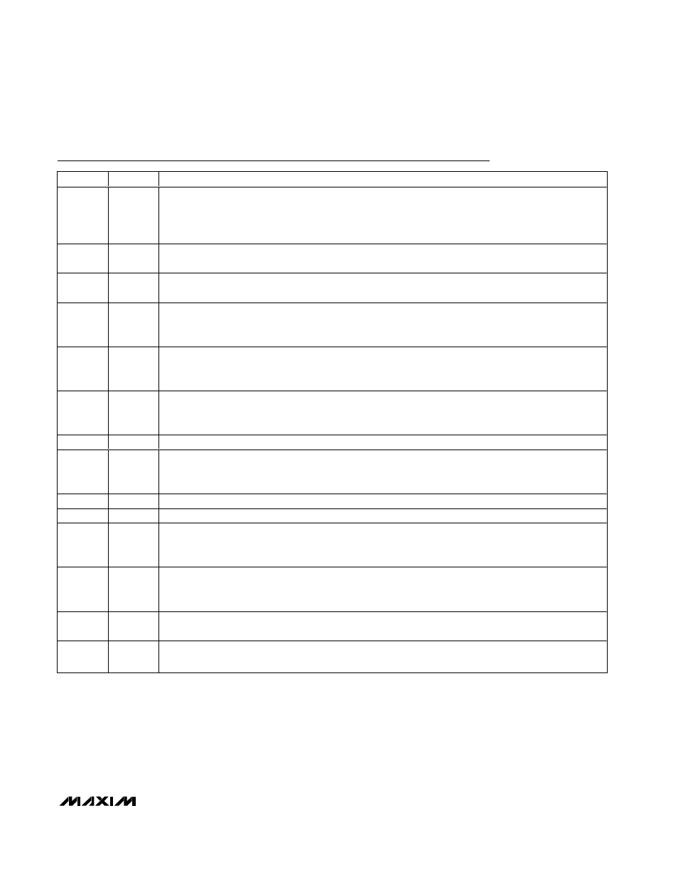
Pin Description
PIN
NAME
FUNCTION
1
ON
On/Off-Control Input. ON sets the undervoltage lockout threshold and resets the part after a fault latch.
Drive ON high to enable the device. Drive ON low to disable the device. Connect ON to IN for the default
undervoltage lockout threshold. Connect a resistor-divider from IN to ON and GND to program the desired
undervoltage lockout threshold.
2
FAULT
Current-Fault, Active-Low, Open-Drain Output.
FAULT asserts and latches low after a current-limit/circuit-
breaker fault has exceeded the current-limit/circuit-breaker timeout period (see the
FAULT
section).
3
TIM
Current-Limit/Circuit-Breaker Timeout Adjustment Input. Connect TIM to IN for the default timeout period or
connect a resistor from TIM to GND to program the current-limit/circuit-breaker timeout period.
4
ILIM
Current-Limit/Circuit-Breaker Threshold Input. Leave ILIM open for a 40mV circuit-breaker threshold,
connect to GND for a 50mV circuit-breaker threshold, or connect to IN for a 60mV circuit-breaker threshold
(see the Current Limiting section).
5
LATCH
Latch or Autoretry Fault Management Selection Input. Connect LATCH to IN to select latch-off mode
after a current-limit/circuit-breaker timeout. Connect LATCH to GND for autorestart mode after a current-
limit/circuit-breaker timeout.
6
OR_ADJ
ORing Switch Turn-On Current Threshold Adjustment Input. Select one of three ORing switch turn-on
threshold settings: connect OR_ADJ to GND, connect OR_ADJ to IN, or leave OR_ADJ floating (see the
Power-Supply ORing section).
7, 10, 13
N.C.
No Connection. Not internally connected.
8
ONQ1
ORing Switch Manual Turn-On Input. Drive ONQ1 low to enable power-supply ORing. Drive ONQ1 high
to set GATE1 high to allow reverse current flow. ONQ1 is disabled when V
IN
is below the UVLO threshold,
V
ON
is below the V
ON_REF
threshold, and after a current/circuit-breaker fault.
9
GND
Ground
11
OUT
Output Voltage Sense. Connect to the output.
12
GATE2
Current-Limiter Switch Gate Drive Output. Connect GATE2 to the gate of the 2nd n-channel MOSFET.
GATE2 is a charge pump with a 45µA pullup current to 5.5V (typ) above OUT when active (see the Typical
Operating Circuit).
14
GATE1
ORing Switch Gate-Drive Output. Connect GATE1 to the gate of the 1st n-channel MOSFET. GATE1 is a
charge pump with a 45µA pullup current to 5.5V (typ) above SENSE when active (see the Typical
Operating Circuit).
15
SENSE
Current-Sense Negative Input. Connect a current-sense resistor, R
SENSE,
from IN to SENSE (see the
Typical Operating Circuit).
16
IN
Input Power and Current-Sense Positive Input. Connect IN to the positive terminal of the current-sense
resistor and to the power source (see the Typical Operating Circuit).