Applications information – Rainbow Electronics MAX5943 User Manual
Page 15
MAX5943
FireWire Current Limiter and Low-Drop
ORing Switch Controller
______________________________________________________________________________________
15
The MAX5943 remains in low-current shutdown mode
when V
ON
is below the 0.4V threshold. Low-current
shutdown mode disables the MAX5943 resulting in less
than 10µA supply current. Shutdown places all logic
inputs in a high-impedance state allowing the inputs to
be connected to IN without drawing additional current
from the supply. An internal delay, t
SD
, allows Q1 and
Q2 to be turned off before the MAX5943 enters low-
current shutdown mode.
Fault Status Output (FAULT)
FAULT is a high-voltage open-drain output that pulls low
when a current-limit/circuit-breaker fault shutdown has
occurred. FAULT remains low until the next startup cycle.
Fault Management
The MAX5943 offers either latch or autoretry fault man-
agement configurable by the LATCH input. Connect
LATCH to IN for latch fault management or connect
LATCH to GND for autoretry fault management. In latch
fault management, FAULT latches low, GATE1 and
GATE2 latch off indefinitely. Cycle ON low and then
high to unlatch and restart the MAX5943. However, the
MAX5943 will not enter a startup cycle until t
OFF
has
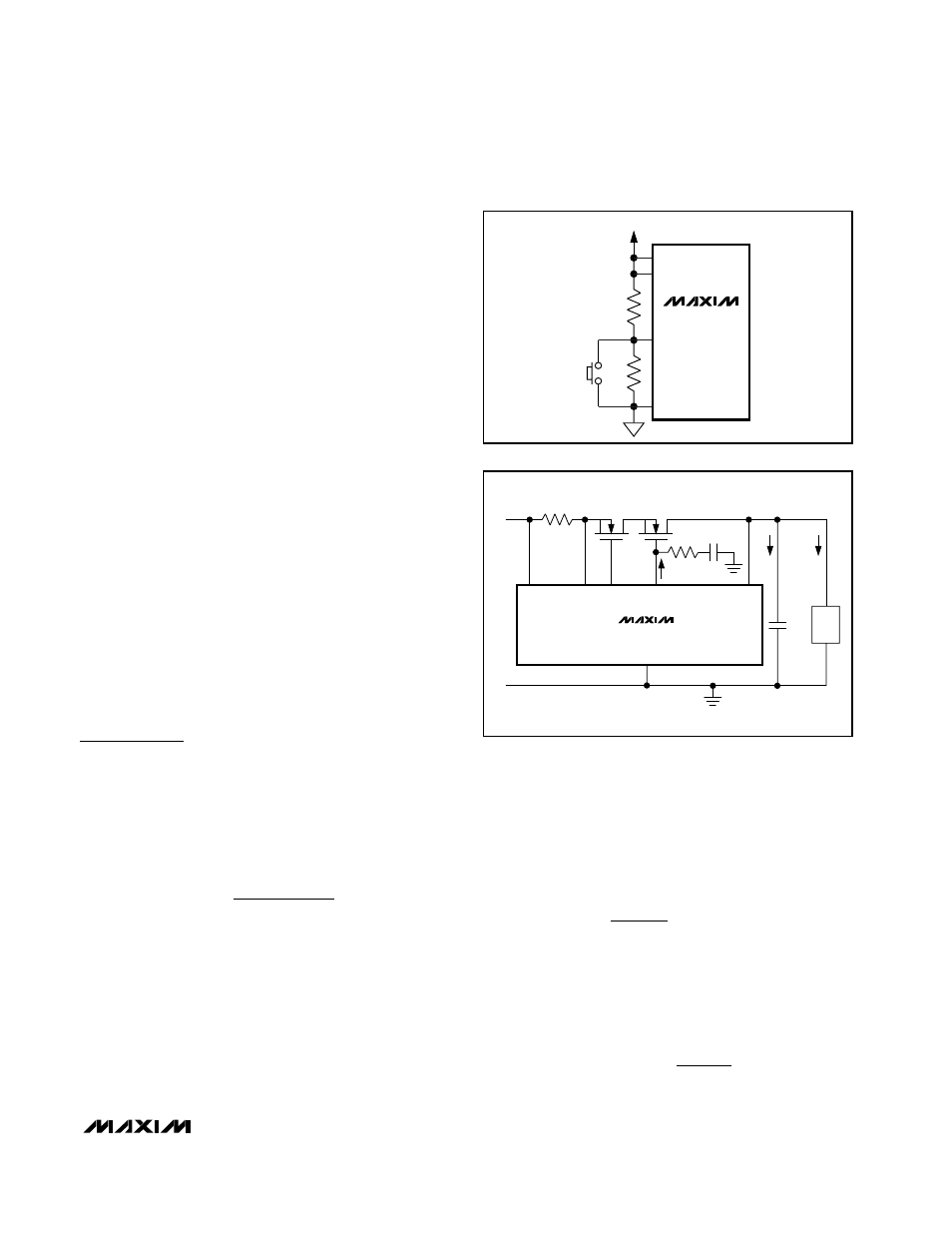
expired. Figure 9 illustrates a way to reset the MAX5943
after a fault using a pushbutton switch.
In autoretry fault management, the MAX5943_ attempt
to restart after a t
OFF
of 128 x t
ILIM
(or 128 x t
CB
) limit-
ing the duty cycle of the MOSFETs to 1/129 under con-
tinuous fault conditions. FAULT deasserts every time a
restart attempt is made.
Applications Information
Startup Consideration
MAX5943A
During startup, a large capacitor at OUT may result in a
charging current equivalent to the current limit. Choose a
current-limit timeout that will allow a successful startup.
The timeout can be approximated using the following
equation:
where I
LIMIT
is the programmed current limit, C
OUT
is
the capacitor at OUT, V
IN
is the supply voltage, and
I
LOAD
is the load current during startup. With IN = 12V,
C
OUT
= 330µF, I
LIMIT
= 1.5A, and I
LOAD
= 0, the
MAX5943 commences by charging the output capacitor
with 1.5A for approximately 2.7ms. Therefore, the
MAX5943A current-limit timeout period (t
ILIM
) should be
greater than 2.7ms for a successful startup. Otherwise,
the MAX5943A powers up in fault management mode
by exceeding the current-limit timeout period.
MAX5943B–MAX5943E
The MAX5943B–MAX5943E do not control the inrush
current during startup. Inrush current control can be
implemented by placing a resistor and capacitor at
GATE2 (Figure 10) to slowly ramp up the gate voltage,
thus limiting the inrush current. The inrush current can
be approximated using the following formula:
Where I
G2U
is GATE2’s 45µA sourcing current and
I
LOAD
is the load current at startup.
To prevent the MAX5943B–MAX5943E from starting up
in a fault condition set:
I
V
R
INRUSH
TH
SENSE
<
I
C
C
I
I
INRUSH
OUT
GATE
G U
LOAD
=
×
+
2
2
t
C
V
I
I
ILIM
OUT
IN
LIMIT
LOAD
>
×
−
MAX5943
R2
R1
V
IN
IN
LATCH
GND
ON
Figure 9. Resetting MAX5943 After a Latched Fault Condition
Q1
Q2
C
GATE
C
OUT
R
SENSE
SENSE GATE1
GATE2
GND
OUT
LOAD
45µA
IN
+
-
V
IN
I
C
I
LOAD
MAX5943B–MAX5943E
1kΩ
Figure 10. Controlling the MAX5943B–MAX5943E Inrush Current