Rainbow Electronics MAX5943 User Manual
Page 13
MAX5943
FireWire Current Limiter and Low-Drop
ORing Switch Controller
______________________________________________________________________________________
13
Timing accuracy is guaranteed for R
TIM
ranging from
4kΩ to 50kΩ. Large R
TIM
values can be used, which
reduces timing accuracy. A maximum timeout period is
enforced to prevent arbitrarily long operation in current-
limit/circuit-breaker conditions.
Long durations in current-limit/circuit-breaker mode
may produce excessive heating and electrical stresses
in R
SENSE
, Q1, Q2, and any other components in the
power path. Use component values rated to handle
electrical stresses during the timeout period.
Power-Supply ORing (ONQ1 = Low)
GATE1 controls the MAX5943 ORing function. The
MAX5943 accomplishes a very-low-voltage-drop diode
ORing function using an n-channel power MOSFET, Q1.
Initially, GATE1 is off (ONQ1 = low) and the load current
conducts through the body diode of Q1 (Figure 4).
GATE1 rises to 5.5V above SENSE when V
IS
exceeds
V
OR
, enhancing Q1. Q1’s low R
DS(ON)
provides a very-
low-voltage drop across its source to drain, reducing volt-
age drop, power dissipation, and heat generation in the
power-supply path created by a traditional diode.
The MAX5943 continuously monitors the load current
by the voltage drop, V
IS
, across the current-sensing
resistor. Q1 turns off rapidly when V
IS
decreases below
V
OR
minus its hysteresis.
Set the MAX5943 ORing threshold (V
OR
) by connecting
OR_ADJ to GND for a 5mV threshold, or to IN for a
10mV threshold, or leave it open for a 7.5mV threshold.
Connect ONQ1 to GND for normal ORing function.
Drive ONQ1 high to force Q1 on, regardless of the load
current condition, as long as the voltages at IN and ON
exceed V
UVLO
and V
ON_REF
, respectively, and the
device is not in a current fault shutdown.
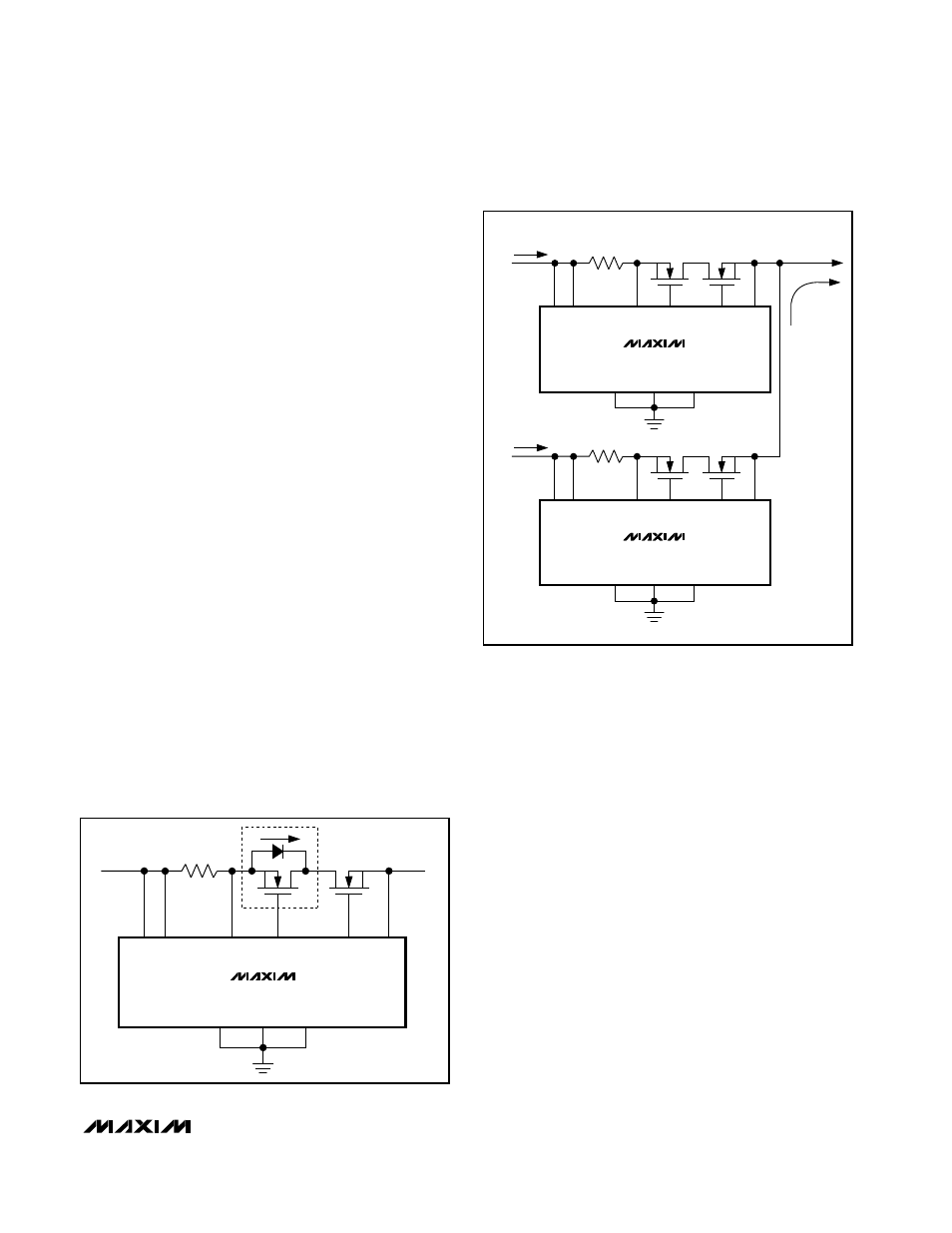
When a higher voltage supply is connected at OUT
(Figure 5), the sense voltage drops below the program-
mable ORing threshold. The MAX5943 immediately
turns off Q1, blocking reverse current flow from OUT to
IN. The power is then routed from the higher supply
input to the load (Figure 6).
Reverse Current Override (ONQ1 = High)
Drive ONQ1 high to disable the power-supply ORing
function. Disabling the MAX5943 ORing function allows
reverse current flow through the power-supply system.
When ONQ1 is high, GATE1 remains fully enhanced as
long as V
IN
is greater than V
UVLO
, V
ON
is above the
V
ON_REF
threshold, and the MAX5943 is not in a cur-
rent-limit or circuit-breaker fault condition. The MAX5943
reverse-current flow feature permits a higher voltage
source connected to one port to route power to another
port, as long as the voltage at IN remains above the
minimum 7.5V operating range (see Figure 7).
SENSE
GATE1
OR_ADJ
ONQ1
GND
GATE2
OUT
Q1
Q2
IN
TO
FireWire
PORT
MAX5943
ON
V
IN
R
SENSE
+ V
IS
-
Figure 4. Q1 Current Path During Inital Startup
I
LOAD
R
SENSE
SENSE GATE1
OR_ADJ
ONQ1
GND
GATE2
OUT
IN
V
INA
V
INB
> V
INA
FROM
BATTERY
SOURCE
TO FireWire
PORT
I
INA
= 0
MAX5943
ON
R
SENSE
SENSE GATE1
OR_ADJ
ONQ1
GND
GATE2
OUT
IN
V
INB
FROM
POWER
SOURCE
I
INB
MAX5943
ON
Figure 5. MAX5943 ORing Controller Rerouting Load Current