Absolute maximum ratings, Dc electrical characteristics – Rainbow Electronics MAX6613 User Manual
Page 2
MAX6613
Low-Voltage Analog Temperature
Sensor in an SC70 Package
2
_______________________________________________________________________________________
ABSOLUTE MAXIMUM RATINGS
Stresses beyond those listed under “Absolute Maximum Ratings” may cause permanent damage to the device. These are stress ratings only, and functional
operation of the device at these or any other conditions beyond those indicated in the operational sections of the specifications is not implied. Exposure to
absolute maximum rating conditions for extended periods may affect device reliability.
Note 1: All parameters tested at room temperature. Values through temperature limits are guaranteed by design.
Note 2: V
OUT
= -0.0000022
✕
T
2
- 0.0115
✕
T + 1.8639 (T = temperature in degrees Celsius).
Note 3: Guaranteed by design to 3 sigma.
Note 4: Guaranteed by design.
(All Voltages Referenced to GND, Unless Otherwise Noted.)
V
CC
to GND ..............................................................-0.3V to +6V
All Other Pins to GND.................................-0.3V to (V
CC
+ 0.3V)
OUT Short to GND......................................................Continuous
Output Current ....................................................-1mA to +50mA
ESD Protection (Human Body Model)................................2000V
Continuous Power Dissipation (T
A
= +70°C)
5-Pin SC70 (derate 3.1mW/°C above +70°C) ...........246.9mW
Operating Temperature Range .........................-55
°C to +130°C
Junction Temperature ......................................................+150°C
Storage Temperature Range .............................-65°C to +150°C
Lead Temperature (soldering 10s) ..................................+300°C
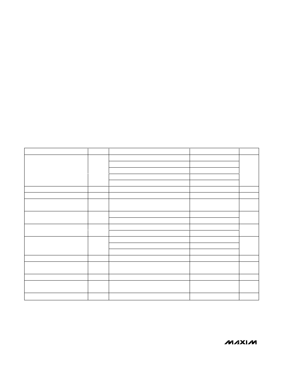
DC ELECTRICAL CHARACTERISTICS
(V
CC
= 1.8V to 5.5V, T
A
= -55°C to +130°C. Typical values are at T
A
= +25°C, unless otherwise noted.) (Note 1)
PARAMETER
SYMBOL
CONDITIONS
MIN
TYP
MAX
UNITS
V
CC
= 2.7V, T
A
= 0°C to +50°C
-1.3
+1.3
V
CC
= 2.7V, T
A
= -20°C to +85°C
-2
+2
V
CC
= 2.7V, T
A
= -55°C to +100°C
-2.4
+2.4
V
CC
= 2.7V, T
A
= +100°C to +125°C
-2.8
+2.8
Temperature-to-Voltage Error
(Notes 2, 3)
V
CC
= 2.7V, T
A
= +125°C to +130°C
-3.1
+3.1
°C
Output Voltage
T
A
= 0°C
1.8455
V
Nonlinearity
T
A
= -55°C to +100°C
±0.4
%
Sensor Gain (Temperature
Sensitivity or Average Slope)
T
A
= -20°C to +100°C (Note 3)
-10.98
-11.23
-11.47
mV/
°C
0 < I
L
< 16µA, T
A
= -55°C to +125°C
160
Maximum Output Impedance
0 < I
L
< 16µA, T
A
= +125°C to +130°C
300
Ω
0 < I
L
< 16µA, T
A
= -55°C to +125°C
-2.5
Load Regulation
0 < I
L
< 16µA, T
A
= 125°C to 130°C
-4.8
mV
T
A
= -20°C to +130°C, V
CC
≤ 5.5V
1
3.3
T
A
= -55°C to -20°C, V
CC
≤ 4.5V
1
4.7
Supply Sensitivity (Note 3)
T
A
= -55°C to -20°C, V
CC
≤ 5.5V
1
mV/V
Quiescent Current
I
Q
No load
7.5
13
µA
Capacitive Load
No sustained oscillations for capacitive
loads in this range (Note 4)
0
1000
pF
Long-Term Stability
T
A
= room temperature for 1000hr (Note 4)
0.1
°C
Temperature Coefficient of
Supply Current
15
nA/
°C
Power-Down Supply Current
V
CC
< 0.8V
0.1
µA