Applications information, Chip information – Rainbow Electronics MAX5382 User Manual
Page 11
are supported. RESTART protocol is supported, but an
immediate STOP condition is necessary to update the
DAC. The 8th bit of the address byte, typically used to
indicate a read or write protocol, is used in the MAX5380/
MAX5381/MAX5382 to enter or exit shutdown mode.
When MAX5380/MAX5381/MAX5382 are addressed in
I
2
C read mode, they enter shutdown mode.
Applications Information
Digital Inputs and Interface Logic
The serial 2-wire interface has logic levels defined as
V
IL
= 0.3
x
V
DD
and V
IH
= 0.7
x
V
DD
. All inputs include
Schmitt trigger buffers to accept slow-transition inter-
faces. This means that optocouplers can interface
directly to the MAX5380/MAX5381/MAX5382 without
additional external logic. The digital inputs are compati-
ble with CMOS logic levels and must not be driven with
voltages higher than V
DD
.
Power-Supply Bypassing and Layout
Careful printed circuit board layout is important for best
system performance. To reduce crosstalk and noise
injection, keep analog and digital signals separate.
Ensure that the ground return from GND to the supply
ground is short and low impedance; a ground plane is
recommended. Bypass V
DD
with a 0.1µF capacitor to
ground as close as possible to the device. If the supply
is excessively noisy, connect a 10
Ω resistor in series
with the supply and V
DD
and add additional capaci-
tance.
MAX5380/MAX5381/MAX5382
Low-Cost, Low-Power, 8-Bit DACs with
2-Wire Serial Interface in SOT23
______________________________________________________________________________________
11
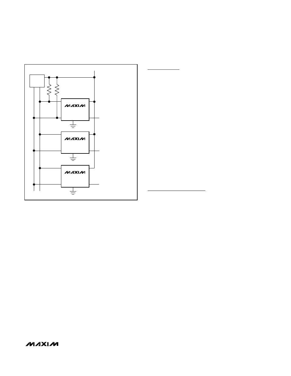
µC
SDA SCL
V
DD
OFFSET ADJUSTMENT
THRESHOLD ADJUSTMENT
GAIN ADJUSTMENT
SCL
SDA
V
DD
OUT
MAX5380L
2V REFERENCE
SCL
SDA
V
DD
OUT
MAX5381M
4V REFERENCE
SCL
SDA
V
DD
OUT
MAX5382N
V
DD
REFERENCE
Figure 7. Typical I
2
C Application
TRANSISTOR COUNT: 2910
Chip Information