Chip information – Rainbow Electronics MAX4884 User Manual
Page 11
electrical ground connection or ground return. Use GND
(pin 6) as the only electrical ground connection.
ESD Test Conditions
ESD performance depends on a number of conditions.
The MAX4881–MAX4884 is specified for 15kV typical
ESD resistance on IN when IN is bypassed to ground
with a 1µF low-ESR ceramic capacitor. Contact Maxim
for a reliability report that documents test setup,
methodology, and results.
Human Body Model
Figure 8 shows the Human Body Model and Figure 9
shows the current waveform it generates when dis-
charged into a low impedance. This model consists of
a 100pF capacitor charged to the ESD voltage of inter-
est, which is then discharged into the device through a
1.5k
Ω resistor.
IEC 61000-4-2
Since January 1996, all equipment manufactured
and/or sold in the European community has been
required to meet the stringent IEC 61000-4-2 specifica-
tion. The IEC 61000-4-2 standard covers ESD testing
and performance of finished equipment; it does not
specifically refer to integrated circuits. The
MAX4881–MAX4884 help users design equipment that
meets Level 3 of IEC 61000-4-2, without additional
ESD-protection components.
The main difference between tests done using the
Human Body Model and IEC 61000-4-2 is higher peak
current in IEC 61000-4-2. Because series resistance is
lower in the IEC 61000-4-2 ESD test model (Figure 10),
the ESD-withstand voltage measured to this standard is
generally lower than that measured using the Human
Body Model. Figure 11 shows the current waveform for
the ±8kV, IEC 61000-4-2, Level 4, ESD Contact
Discharge test. The Air-Gap test involves approaching
the device with a charger probe. The Contact
Discharge method connects the probe to the device
before the probe is energized.
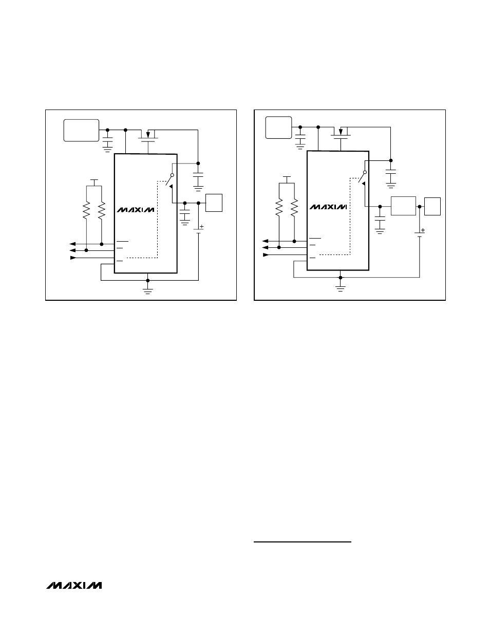
Typical Operating Circuits
Figures 12 and 13 depict some typical connections to
the MAX4881–MAX4884. Figure 12 shows a battery
charger application where the source power is an 4.4V
adapter with a built-in charger, while Figure 13 shows
an application where the battery charger is external.
Chip Information
TRANSISTOR COUNT: 2391
PROCESS: BiCMOS
MAX4881–MAX4884
Overvoltage Protection Controllers with
Current Limit in TDFN
______________________________________________________________________________________
11
AC-DC
ADAPTER
5.25V
GATE
IN
FLAGI
OV
Li+
BTB
BTA
1.1A/0.7A
CB
EN
GND
LOAD
V
IO
MAX4881/
MAX4883
BATTERY
CHARGER
Figure 13. Connection to an AC-DC Adapter with a Built-In
Battery Charger
4.4V ADAPTER
WITH BUILT-IN
CHARGER
GATE
IN
FLAGI
OV
Li+
BTB
BTA
1.1A/0.7A
CB
EN
GND
LOAD
V
IO
MAX4882/
MAX4884
Figure 12. Connection to an AC-DC Adapter without a Built-In
Battery Charger