Rainbow Electronics MAX16040 User Manual
Page 15
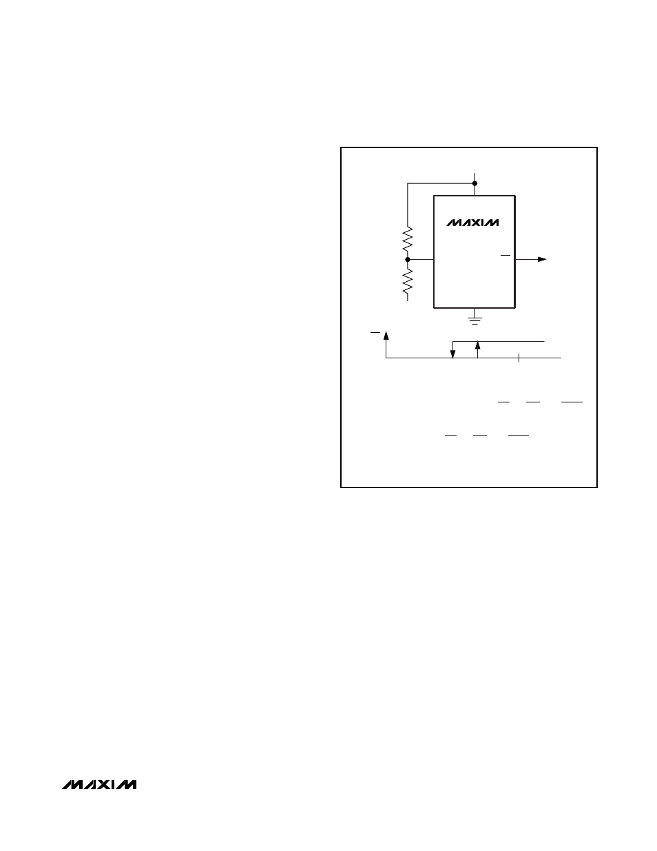
Monitoring a Negative Voltage
Connect the circuit as shown in Figure 9 to use the
power-fail comparator to monitor a negative supply rail.
PFO stays low when V- is good. When V- rises to cause
PFI to be above +1.235V, PFO goes high. Ensure V
CC
comes up before the negative supply.
Negative-Going V
CC
Transients
The MAX16033–MAX16040 are relatively immune to
short-duration, negative-going V
CC
transients.
Resetting the µP when V
CC
experiences only small
glitches is not usually desired.
The
Typical Operating Characteristics
section contains
a Maximum Transient Duration vs. Reset Threshold
Overdrive graph. The graph shows the maximum pulse
width of a negative-going V
CC
transient that would not
trigger a reset pulse. As the amplitude of the transient
increases (i.e., goes further below the reset threshold
voltage), the maximum allowable pulse width decreas-
es. Typically, a V
CC
transient that goes 100mV below
the reset threshold and lasts for 25µs does not trigger a
reset pulse.
A 0.1µF bypass capacitor mounted close to V
CC
pro-
vides additional transient immunity.
MAX16033–MAX16040
Low-Power Battery Backup
Circuits in Small µDFN Packages
______________________________________________________________________________________
15
GND
PFI
R2
R1
V-
MAX16033–
MAX16040
3.0V OR 3.3V
V
CC
PFO
PFO
0V
V
L
V-
V
TRIP
Figure 9. Monitoring a Negative Voltage
V
R
V
V
R
R
V
R
V
R
V
R
R
V
R
V
V
V
mV
TRIP
PFT
PFH
CC
L
PFT
CC
PFT
PFH
.
=
+
(
)
+
⎛
⎝
⎜
⎞
⎠
⎟ −
⎡
⎣
⎢
⎤
⎦
⎥
=
(
)
+
⎛
⎝
⎜
⎞
⎠
⎟ −
⎡
⎣
⎢
⎤
⎦
⎥
=
=
2
1
1
1
2
1
2
1
1
1
2
1
1 235
12