Rainbow Electronics MAX16040 User Manual
Page 13
MAX16033–MAX16040
Low-Power Battery Backup
Circuits in Small µDFN Packages
______________________________________________________________________________________
13
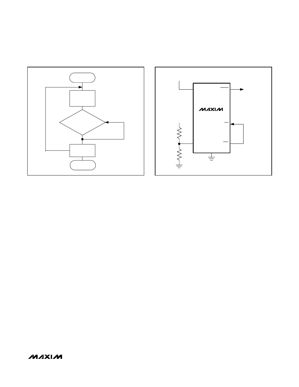
Watchdog Software Considerations
One way to help the watchdog timer to monitor soft-
ware execution more closely is to set and reset the
watchdog at different points in the program, rather than
pulsing the watchdog input periodically. Figure 6
shows a flow diagram where the I/O driving the watch-
dog is set low in the beginning of the program, set high
at the beginning of every subroutine or loop, and set
low again when the program returns to the beginning. If
the program should hang in any subroutine, the watch-
dog would timeout and reset the µP.
Replacing the Backup Battery
Decouple BATT to GND with a 0.1µF capacitor. The
backup power source may be removed while V
CC
remains valid without the danger of triggering a reset
pulse. The device does not enter battery-backup mode
when V
CC
stays above the reset threshold voltage.
Power-Fail Comparator
Monitoring an Additional Power Supply
Monitor another voltage by connecting a resistive divider
to PFI as shown in Figure 7. The threshold voltage is:
V
TH(PFI)
= 1.235 (R1 / R2 + 1)
where V
TH(PFI)
is the threshold at which the monitored
voltage will trip PFO.
To simplify the resistor selection, choose a value for R2
and calculate R1.
R1 = R2 [(V
TH(PFI)
/ 1.235) - 1]
Connect PFO to MR in applications that require RESET to
assert when the second voltage falls below its threshold.
RESET remains asserted as long as PFO holds MR low,
and for 140ms (min) after PFO goes high.
Adding Hysteresis to the Power-Fail Comparator
The power-fail comparator provides a typical hysteresis
of 12mV, which is sufficient for most applications where
a power-supply line is being monitored through an
external voltage-divider. Connect a voltage-divider
between PFI and PFO as shown in Figure 8a to provide
additional noise immunity. Select the ratio of R1 and R2
such that V
PFI
falls to 1.235V when V
IN
drops to its trip
point, V
TRIP
. R3 adds hysteresis and is typically more
than 10 times the value of R1 or R2. The hysteresis win-
dow extends above (V
H
) and below (V
L
) the original trip
point, V
TRIP
. Connecting an ordinary signal diode in
series with R3 as shown in Figure 8b causes the lower
trip point (V
L
) to coincide with the trip point without hys-
teresis (V
TRIP
). This method provides additional noise
margin without compromising the accuracy of the
power-fail threshold when the monitored voltage is
falling. Set the current through R1 and R2 to be at least
10µA to ensure that the 100nA (max) PFI input current
does not shift the trip point. Set R3 to be higher than
10kΩ to reduce the load at PFO. Capacitor C1 adds
additional noise rejection.
SET
WDI
LOW
SUBROUTINE
OR PROGRAM LOOP
SET
WDI HIGH
RETURN
END
START
GND
V
CC
V+
V
CC
RESET
TO µP
PFI
R1
R2
MAX16033–
MAX16040
MR
PFO
Figure 6. Watchdog Flow Diagram
Figure 7. Monitoring an Additional Power Supply