Rainbow Electronics MAX16040 User Manual
Page 10
MAX16033–MAX16040
Low-Power Battery Backup
Circuits in Small µDFN Packages
10
______________________________________________________________________________________
Backup Battery Switchover
To preserve the contents of the RAM in a brownout or
power failure, the MAX16033–MAX16040 automatically
switch to back up the battery installed at BATT when
the following two conditions are met:
1) V
CC
falls below the reset threshold voltage.
2) V
CC
is below V
BATT
.
Table 1 lists the status of the inputs and outputs in bat-
tery-backup mode. The devices do not power-up if the
only voltage source is V
BATT
. OUT only powers up from
V
CC
at startup.
Manual-Reset Input
(MAX16033/MAX16037 Only)
Many µP-based products require manual-reset capabil-
ity, allowing the user or external logic circuitry to initiate
a reset. For the MAX16033/MAX16037, a logic-low on
MR asserts RESET. RESET remains asserted while MR
is low and for a minimum of 140ms (t
RP
) after it returns
high. MR has an internal 20kΩ (min) pullup resistor to
V
CC
. This input can be driven from TTL/CMOS logic
outputs or with open-drain/collector outputs. Connect a
normally-open momentary switch from MR to GND to
create a manual-reset function; external debounce cir-
cuitry is not required. When driving MR from long
cables or when using the device in a noisy environ-
ment, connect a 0.1µF capacitor from MR to GND to
provide additional noise immunity.
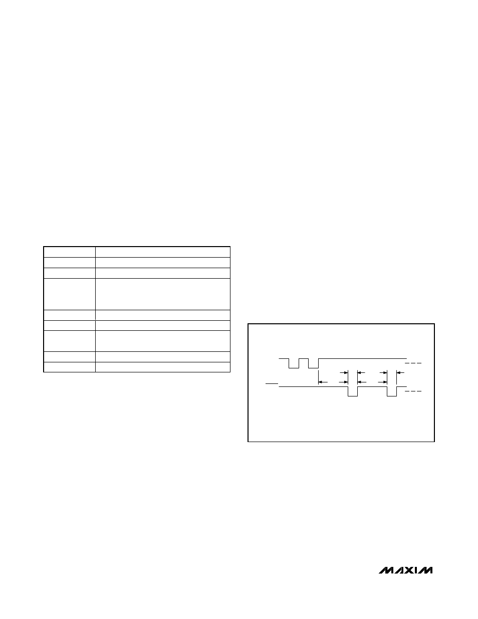
Watchdog Input
(MAX16034/MAX16038 Only)
The watchdog monitors µP activity through the watch-
dog input (WDI). RESET asserts when the µP fails to
toggle WDI. Connect WDI to a bus line or µP I/O line. A
change of state (high to low, low to high, or a minimum
100ns pulse) resets the watchdog timer. If WDI remains
high or low for longer than the watchdog timeout period
(t
WD
), the internal watchdog timer runs out and triggers
a reset pulse for the reset timeout period (t
RP
). The
internal watchdog timer clears whenever reset is
asserted or whenever WDI sees a rising or falling edge.
If WDI remains in either a high or low state, a reset
pulse periodically asserts after every watchdog timeout
period (t
WD
); see Figure 2.
Table 1. Input and Output Status in
Battery-Backup Mode
PIN
STATUS
V
CC
Disconnected from OUT
OUT
Connected to BATT
BATT
Connected to OUT. Current drawn from the
battery is less than 1µA (at V
BATT
= 2.8V,
excluding I
OUT
) when V
CC
= 0V.
RESET
Asserted
BATTON
High state
MR, RESETIN,
CEIN, and WDI
Inputs ignored
CEOUT
Connected to OUT
PFO
Asserted
t
WD
= WATCHDOG TIMEOUT PERIOD
t
RP
= RESET TIMEOUT PERIOD
WDI
RESET
t
WD
t
WD
t
RP
t
RP
Figure 2. MAX16034/MAX16038 Watchdog Timeout Period and
Reset Active Time