Pin description – Rainbow Electronics MAX5068 User Manual
Page 8
MAX5068
High-Frequency, Current-Mode PWM Controller
with Accurate Programmable Oscillator
8
_______________________________________________________________________________________
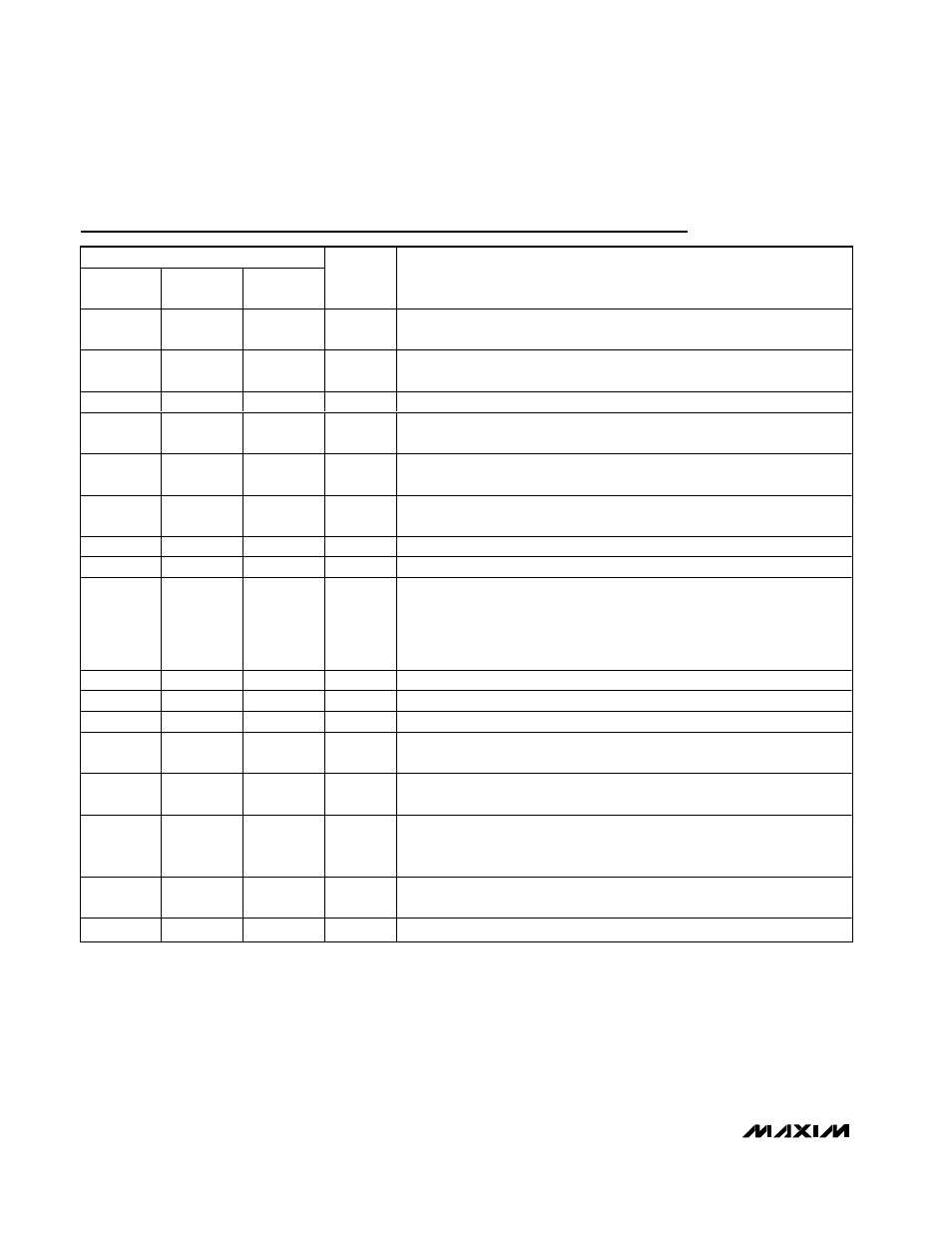
Pin Description
PIN
MAX5068A
MAX5068B
MAX5068C
MAX5068E
MAX5068D
MAX5068F
NAME
FUNCTION
1
1
1
RT
Oscillator-Timing Resistor Connection. Connect a resistor from RT to AGND
to set the internal oscillator frequency.
2
2
—
SYNC
External-Clock Sync Input. Connect SYNC to AGND when not using an
external clock.
3
—
2
HYST
Programmable Hysteresis Input
—
3
3
SCOMP
Slope-Compensation Capacitor Input. Connect a capacitor to AGND to set
the slope compensation.
4
4
4
DT
Dead-Time Adjustment. Connect a resistor from DT to AGND to adjust NDRV
dead time. Connect to REG5 for maximum duty cycle.
5
5
5
UVLO/EN
Externally Programmable Undervoltage Lockout. UVLO/EN programs the
input start voltage. Drive UVLO/EN to AGND to disable the output.
6
6
6
FB
Error-Amplifier Inverting Input
7
7
7
COMP
Error-Amplifier Compensation Output
8
8
8
FLTINT
Fault-Integration Input. A capacitor connected to FLTINT charges with an
internal 60µA current source during repeated current-limit events. Switching
terminates when V
FLTINT
reaches 2.9V. An external resistor connected in
parallel discharges the capacitor. Switching resumes when V
FLTINT
drops to
1.6V.
9
9
9
CS
Current-Sense Resistor Connection
10, 12
10, 12
10, 12
AGND
Analog Ground. Connect to PGND through a ground plane.
11
11
11
PGND
Power Ground. Connect to AGND through a ground plane.
13
13
13
NDRV
G ate- D r i ver O utp ut. C onnect the N D RV outp ut to the g ate of the exter nal
N - channel FE T.
14
14
14
V
CC
9V Linear-Regulator Output. Decouple V
CC
with a minimum 1µF ceramic
capacitor to the AGND plane; also internally connected to the FET driver.
15
15
15
IN
Power-Supply Input. IN provides power for all internal circuitry. Decouple IN
with a minimum 0.1µF ceramic capacitor to AGND (see the Typical
Operating Circuit).
16
16
16
REG5
5V Linear-Regulator Output. Decouple to AGND with a 0.1µF ceramic
capacitor.
EP
EP
EP
PAD
Exposed Pad. Connect to GND.