Max5068 – Rainbow Electronics MAX5068 User Manual
Page 14
MAX5068
Use the following formula to calculate the internal oscil-
lator frequency:
where f
OSC
is the oscillator frequency and R
RT
is a
resistor connected from RT to AGND.
Choose the appropriate resistor at RT to calculate the
desired output switching frequency (f
SW
):
The MAX5068A/B and the MAX5068C/D/E/F have pro-
grammable output switching frequencies from 25kHz to
1.25MHz and 12.5kHz to 625kHz, respectively.
Dead-Time Adjustment
The MAX5068 programmable dead-time function
(Figure 7) allows additional flexibility in optimizing mag-
netics design and overcoming parasitic effects. The
MAX5068A/B and the MAX5068C/D/E/F have a maxi-
mum 50% and 75% duty cycle, respectively. In many
applications, the duty cycle of the external MOSFET
may need to be slightly decreased to prevent satura-
tion in the transformer’s primary. The dead time can be
configured from 30ns to 1 / (0.5 x f
SW
) when program-
ming the MAX5068. Connect a resistor between DT and
AGND to set the desired dead time using the following
formula:
where R
DT
is in k
Ω
and the dead time is in ns.
Connect DT to REG5 to remove the delay and achieve
the MAX5068 maximum duty cycles.
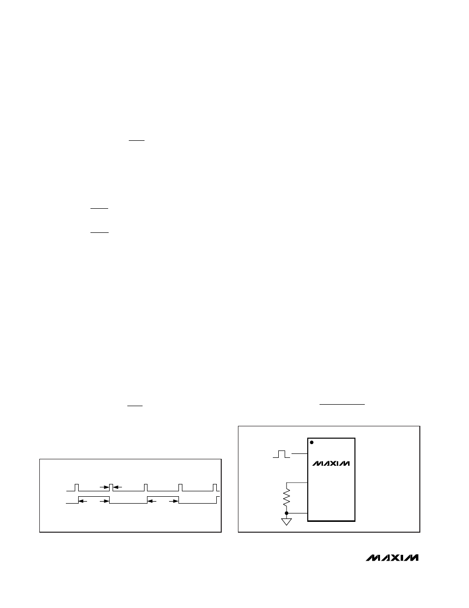
External Synchronization
(MAX5068A/B/C/E)
The MAX5068A/B/C/E can be synchronized using an
external clock at the SYNC input. For proper frequency
synchronization, the SYNC’s input frequency must be at
least 25% higher than the MAX5068A/B/C/E pro-
grammed internal oscillator frequency. Connect SYNC
to AGND when not using an external clock.
Integrating Fault Protection
The integrating fault-protection feature allows transient
overcurrent conditions to be ignored for a programma-
ble amount of time, giving the power supply time to
behave like a current source to the load. For example,
this can occur under load current transients when the
control loop requests maximum current to keep the out-
put voltage from going out of regulation. Program the
fault-integration time by connecting an external suitably
sized capacitor to the FLTINT. Under sustained over-
current faults, the voltage across this capacitor ramps
up towards the FLTINT shutdown threshold (typically
2.8V). Once the threshold is reached, the power supply
shuts down. A high-value bleed resistor connected in
parallel with the FLTINT capacitor allows it to discharge
towards the restart threshold (typically 1.6V). Once this
threshold is reached, the supply restarts with a new
soft-start cycle.
Note that cycle-by-cycle current limiting is provided at
all times by CS with a threshold of 314mV (typ). The
fault-integration circuit forces a 60µA current onto
FLTINT each time that the current-limit comparator is
tripped (see the Functional Diagram). Use the following
formula to calculate the value of the capacitor neces-
sary for the desired shutdown time of the circuit:
C
I
x t
V
FLTINT
FLTINT
SH
.
≅
2 8
Dead time
R
ns
DT
.
(
)
=
×
60
29 4
RT
SW
RT
SW
R
f
for the MAX
A B and
R
f
for the MAX
C D E F
/
/
/ /
=
=
10
2
5068
10
4
5068
11
11
f
R
osc
RT
=
10
11
High-Frequency, Current-Mode PWM Controller
with Accurate Programmable Oscillator
14
______________________________________________________________________________________
DEAD TIME
NDRV
t
DT
< 50%
< 50%
Figure 7. MAX5068 NDRV Dead-Time Timing Diagram
MAX5068A/B/C/E
AGND
RT
SYNC
Figure 8. External Synchronization of the MAX5068A/B/C/E