Max5068 – Rainbow Electronics MAX5068 User Manual
Page 12
MAX5068
During startup, the UVLO circuit keeps the PWM com-
parator, ILIM comparator, oscillator, and output driver
shut down to reduce current consumption. Once V
IN
reaches 23.6V, the UVLO circuit turns on both the PWM
and ILIM comparators, as well as the oscillator, and
allows the output driver to switch. When V
IN
drops
below 9.7V, the UVLO circuit shuts down the PWM
comparator, ILIM comparator, oscillator, and output dri-
ver returning the MAX5068A/C/D to the startup mode.
MAX5068A/C/D Startup Operation
Normally, V
IN
is derived from the tertiary winding of the
transformer. However, at startup there is no energy
delivered through the transformer, hence, a special
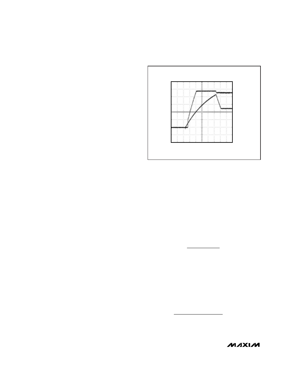
bootstrap sequence is required. Figure 5 shows the
voltages on V
IN
and V
CC
during startup. Initially, both
V
IN
and V
CC
are zero. After the input voltage is applied,
C1 charges through the startup resistor, R1, to an inter-
mediate voltage (see Figure 1). At this point, the inter-
nal regulator begins charging C3 (see Figure 5). Only
47µA of the current supplied by R1 is used by the
MAX5068A/C/D. The remaining input current charges
C1 and C3. The charging of C3 stops when the V
CC
voltage reaches approximately 9.5V. The voltage
across C1 continues rising until it reaches the wake-up
level of 23.6V. Once V
IN
exceeds the bootstrap UVLO
threshold, NDRV begins switching the MOSFET and
energy is transferred to the secondary and tertiary out-
puts. If the voltage on the tertiary output builds to high-
er than 9.74V (the bootstrap UVLO lower threshold),
startup ends and sustained operation commences.
If V
IN
drops below 9.74V before startup is complete, the
device goes back to low-current UVLO. If this occurs,
increase the value of C1 to store enough energy to
allow for the voltage at the tertiary winding to build up.
Startup Time Considerations for
Power Supplies Using the MAX5068A/C/D
The V
IN
bypass capacitor, C1, supplies current imme-
diately after wakeup (see Figure 1). The size of C1 and
the connection configuration of the tertiary winding
determine the number of cycles available for startup.
Large values of C1 increase the startup time and also
supply extra gate charge for more cycles during initial
startup. If the value of C1 is too small, V
IN
drops below
9.74V because NDRV does not have enough time to
switch and build up sufficient voltage across the tertiary
output that powers the device. The device goes back
into UVLO and does not start. Use low-leakage capaci-
tors for C1 and C3.
Generally, offline power supplies keep typical startup
times to less than 500ms, even in low-line conditions
(85V
AC
input for universal offline applications or 36V
DC
for telecom applications). Size the startup resistor, R1,
to supply both the maximum startup bias of the device
(90µA) and the charging current for C1 and C3. The
bypass capacitor, C3, must charge to 9.5V, and C1
must charge to 24V, within the desired time period of
500ms. Because of the internal soft-start time of the
MAX5068, C1 must store enough charge to deliver cur-
rent to the device for at least 2047 oscillator clock
cycles. To calculate the approximate amount of capaci-
tance required, use the following formula:
where I
IN
is the MAX5068’s internal supply current after
startup (2.5mA typ), Q
gtot
is the total gate charge for
Q1, f
SW
is the MAX5068’s programmed switching fre-
quency, V
HYST
is the bootstrap UVLO hysteresis (12V),
and t
ss
is the internal soft-start time (2047 x 1 / f
OSC
).
Example: I
g
= (8nC) (250kHz)
≅
2.0mA
f
OSC
= 2 x 250kHz
Soft-start duration = 2047 x (1 / f
OSC
) = 4.1ms
Use a 2.2µF ceramic capacitor for C1.
C
mA
mA
ms
V
F
1
2 5
2
4 1
12
1 54
( .
) ( .
)
.
=
+
=
µ
I
Q
x f
C
I
I
x t
V
g
gtot
SW
IN
g
SS
HYST
(
)
=
=
+
1
High-Frequency, Current-Mode PWM Controller
with Accurate Programmable Oscillator
12
______________________________________________________________________________________
100ms/div
MAX5068
V
IN
PIN
V
CC
2V/div
0V
5V/div
Figure 5. VIN and VCC During Startup When Using the
MAX5068 in Bootstrapped Mode (Also see Figure 1)