Table 2. setting t – Rainbow Electronics MAX6645 User Manual
Page 6
MAX6643/MAX6644/MAX6645
There are two options for the behavior of the PWM out-
puts at power-up. Option 1 (minimum duty cycle = 0):
at power-up, the PWM duty cycle is zero. Option 2
(minimum duty cycle = the start duty cycle): at power-
up, there is a startup delay, after which the duty cycle
goes to 100% for the spin-up period. After the startup
delay and spin-up, the duty cycle drops to its minimum
value. The minimum duty cycle is in the 0% to 50%
range (see the Selector Guide).
To control fan speed based on temperature, T
HIGH
is
set to the temperature beyond which the fan should spin
at 100%. T
LOW
is set to the temperature below which
the duty cycle can be reduced to its minimum value.
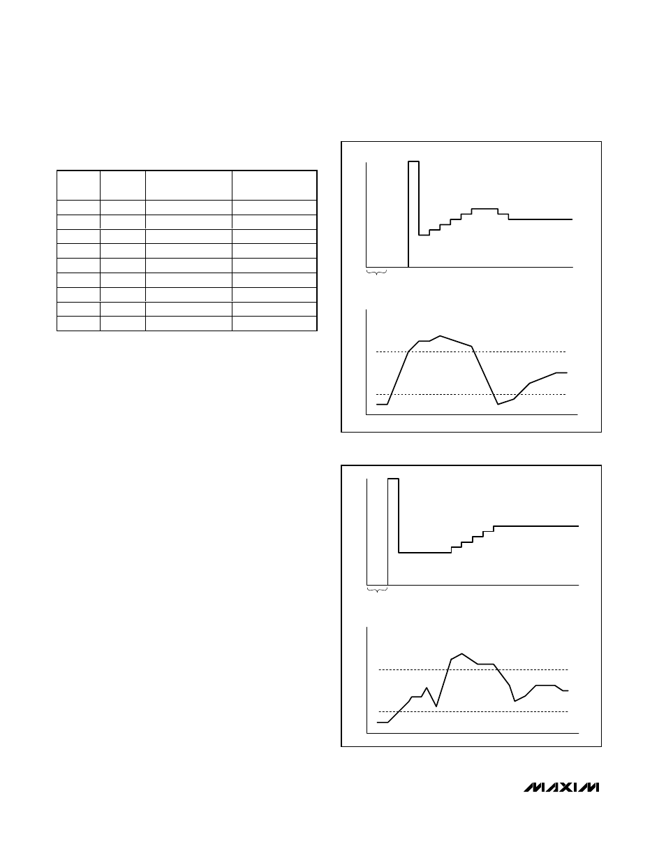
After power-up and spin-up (if applicable), the duty
cycle reduces to its minimum value (either 0% or the
start duty cycle). For option 1 (minimum duty cycle = 0),
if the measured temperature remains below T
HIGH
, the
duty cycle remains at zero (see Figure 1). If the temper-
ature increases above T
HIGH
, the duty cycle goes to
100% for the spin-up period, and then goes to the start
duty cycle (for example, 40%). If the measured temper-
ature remains above T
HIGH
when temperature is next
measured (4s later), the duty cycle begins to increase,
incrementing by 1.5% every 4s until the fan is spinning
fast enough to reduce the temperature below T
HIGH
.
For option 2 (minimum duty cycle = start duty cycle), if
the measured temperature remains below T
HIGH
, the
duty cycle does not increase and the fan continues to
run at a slow speed. If the temperature increases
above T
HIGH
, the duty cycle begins to increase, incre-
menting by 1.5% every 4s until the fan is spinning fast
enough to reduce the temperature below T
HIGH
(see
Figure 2). In both cases, if only a small amount of extra
cooling is necessary to reduce the temperature below
Automatic PWM Fan-Speed Controllers with
Overtemperature Output
6
_______________________________________________________________________________________
Table 2. Setting T
LOW
(MAX6643 and MAX6644)
STARTUP
DUTY CYCLE
TEMPERATURE
TIME
TIME
T
HIGH
SPIN-UP
T
LOW
Figure 1. Temperature-Controlled Duty-Cycle Change with
Minimum Duty Cycle 30%
STARTUP
MAX664_B HAS 30% PWM_OUT DUTY CYCLE DURING STARTUP.
DUTY CYCLE
TEMPERATURE
TIME
TIME
T
HIGH
T
LOW
SPIN-UP
Figure 2. Temperature-Controlled Duty-Cycle Change with
Minimum Duty Cycle 30%
TL2
TL1
T
LOW
(°C)
L SUFFIX
T
LOW
(°C)
H SUFFIX
0
0
15
35
0
High-Z
20
40
0
1
25
45
High-Z
0
30
50
High-Z
High-Z
35
55
High-Z
1
40
60
1
0
45
65
1
High-Z
50
70
1
1
55
75
High-Z = High impedance.