Rainbow Electronics MAX6645 User Manual
Page 2
MAX6643/MAX6644/MAX6645
Automatic PWM Fan-Speed Controllers with
Overtemperature Output
2
_______________________________________________________________________________________
ABSOLUTE MAXIMUM RATINGS
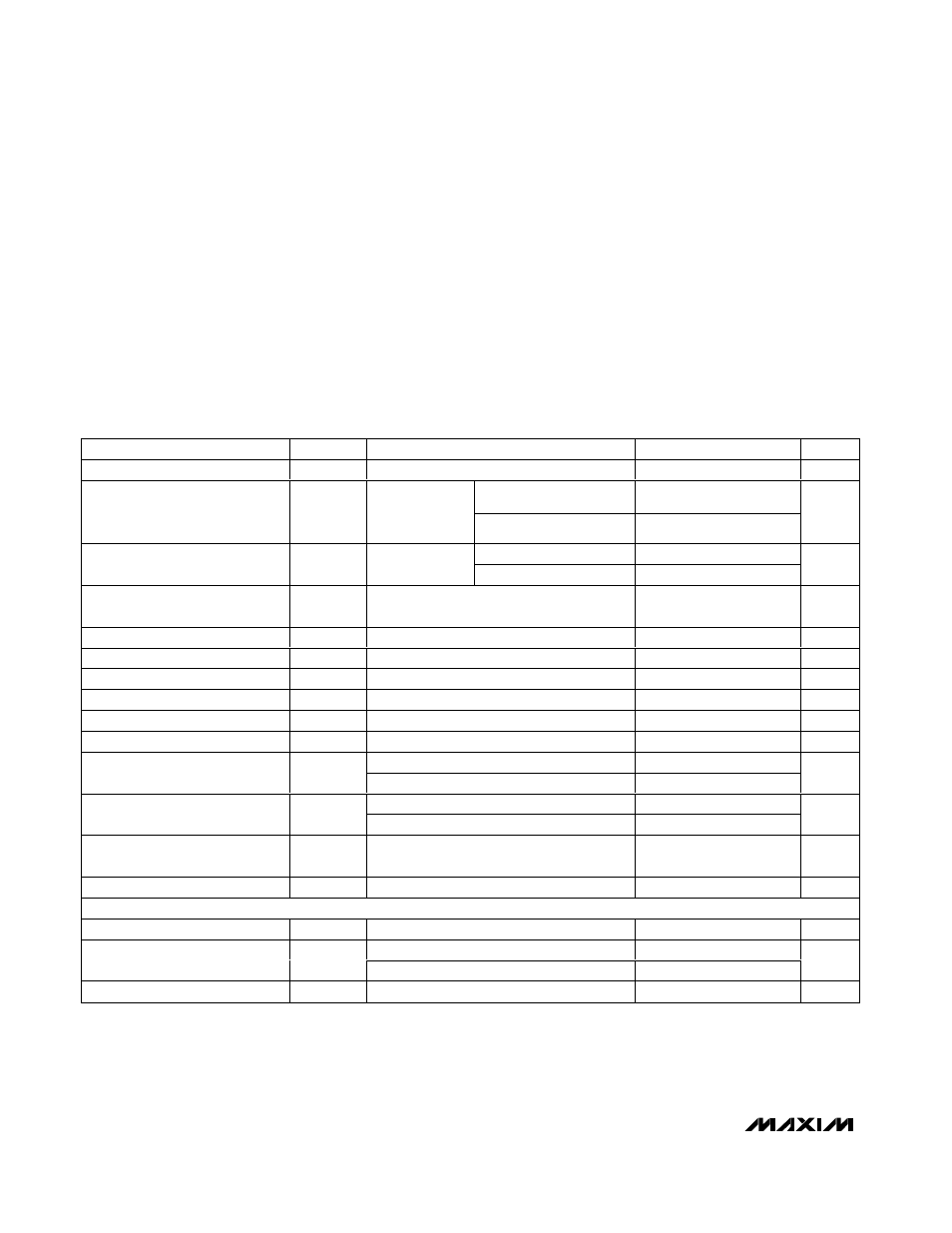
ELECTRICAL CHARACTERISTICS
(V
DD
= +3.0V to +5.5V, T
A
= -40
°C to +125°C, unless otherwise noted. Typical values are at V
DD
= +3.3V, T
A
= +25°C.) (Note 1)
Stresses beyond those listed under “Absolute Maximum Ratings” may cause permanent damage to the device. These are stress ratings only, and functional
operation of the device at these or any other conditions beyond those indicated in the operational sections of the specifications is not implied. Exposure to
absolute maximum rating conditions for extended periods may affect device reliability.
V
DD
to GND ..............................................................-0.3V to +6V
PWM_OUT, OT, and FANFAIL to GND.....................-0.3V to +6V
FAN_IN1 and FAN_IN2 to GND...........................-0.3V to +13.2V
DXP_ to GND.........................................................-0.3V to +0.8V
FULLSPD, FULLSPD, TH_, TL_, TACHSET,
and OT_ to GND ..................................-0.3V to +(V
DD
+ 0.3V)
FANFAIL, OT Current ..........................................-1mA to +50mA
Continuous Power Dissipation (T
A
= +70°C)
10-Pin µMAX (derate 5.6mW/°C above +70°C) ...........444mW
16-Pin QSOP (derate 8.3mW/°C above +70°C).......... 667mW
Operating Temperature Range .........................-40°C to +125°C
Junction Temperature ......................................................+150°C
Storage Temperature Range ............................-65°C to +150°C
Lead Temperature (soldering, 10s) .................................+300°C
PARAMETER
SYMBOL
CONDITIONS
MIN
TYP
MAX
UNITS
Operating Supply Voltage Range
V
DD
+3.0
+5.5
V
T
A
= +20°C to +60°C
±2
Remote Temperature Error
V
DD
= +3.3V,
+20
°C ≤ T
RJ
≤
+100
°C
T
A
= 0°C to +125°C
±3
°C
T
A
= +10°C to +70°C
±2.5
Local Temperature Error
V
CC
= +3.3V
T
A
= 0°C to +125°C
±3.5
°C
Temperature Error from Supply
Sensitivity
±0.2
°C/V
Power-On-Reset (POR) Threshold
V
DD
falling edge
1.5
2.0
2.5
V
POR Threshold Hysteresis
90
mV
Operating Current
I
S
During a conversion
0.5
1
mA
Average Operating Current
Duty cycle = 50%, no load
0.5
mA
Remote-Diode Sourcing Current
High level
80
100
120
µA
Conversion Time
125
ms
MAX664_ _A_ _ _ _
2.5
Spin-Up Time
MAX664_ _B_ _ _ _
8
s
MAX664_ _A_ _ _ _
2.5
Startup Delay
MAX664_ _B_ _ _ _
0.5
s
Minimum Fan-Fail Tachometer
Frequency
16
Hz
PWM_OUT Frequency
F
PWM_OUT
32
Hz
DIGITAL OUTPUTS (
OT
,
FANFAIL
, PWM_OUT)
Output Low Voltage (OT)
V
OL
I
SINK
= 1mA
0.4
V
I
SINK
= 6mA
0.5
Output Low Voltage
(FANFAIL, PWM_OUT)
V
OL
I
SINK
= 1mA
0.4
V
Output-High Leakage Current
I
OH
V
OH
= 3.3V
1
µA