Chip information, Pin configurations – Rainbow Electronics MAX6645 User Manual
Page 13
MAX6643/MAX6644/MAX6645
Automatic PWM Fan-Speed Controllers with
Overtemperature Output
______________________________________________________________________________________
13
in value. Cable resistance also affects remote-sensor
accuracy. A 1
Ω series resistance introduces about
+1/2°C error.
PC Board Layout Checklist
1) Place the MAX6643/MAX6644/MAX6645 as close as
practical to the remote diode. In a noisy environment,
such as a computer motherboard, this distance can
be 4in to 8in or more, as long as the worst noise
sources (such as CRTs, clock generators, memory
buses, and ISA/PCI buses) are avoided.
2) Do not route the DXP lines next to the deflection coils
of a CRT. Also, do not route the traces across a fast
memory bus, which can easily introduce +30°C
error, even with good filtering. Otherwise, most noise
sources are fairly benign.
3) Route the DXP and GND traces parallel and close to
each other, away from any high-voltage traces such
as +12VDC. Avoid leakage currents from PC board
contamination. A 20M
Ω leakage path from DXP to
ground causes approximately +1°C error.
4) Route as few vias and crossunders as possible to
minimize copper/solder thermocouple effects.
5) When introducing a thermocouple, make sure that
both the DXP and the GND paths have matching
thermocouples. In general, PC board-induced ther-
mocouples are not a serious problem. A copper sol-
der thermocouple exhibits 3µV/°C, and it takes
approximately 200µV of voltage error at DXP/GN to
cause a +1°C measurement error, so most parasitic
thermocouple errors are swamped out.
6) Use wide traces. Narrow traces are more inductive
and tend to pick up radiated noise. The 10-mil widths
and spacings are recommended, but are not
absolutely necessary (as they offer only a minor
improvement in leakage and noise), but use them
where practical.
7) Placing an electrically clean copper ground plane
between the DXP traces and traces carrying high-
frequency noise signals helps reduce EMI.
Chip Information
TRANSISTOR COUNT: 12,518
PROCESS: BiCMOS
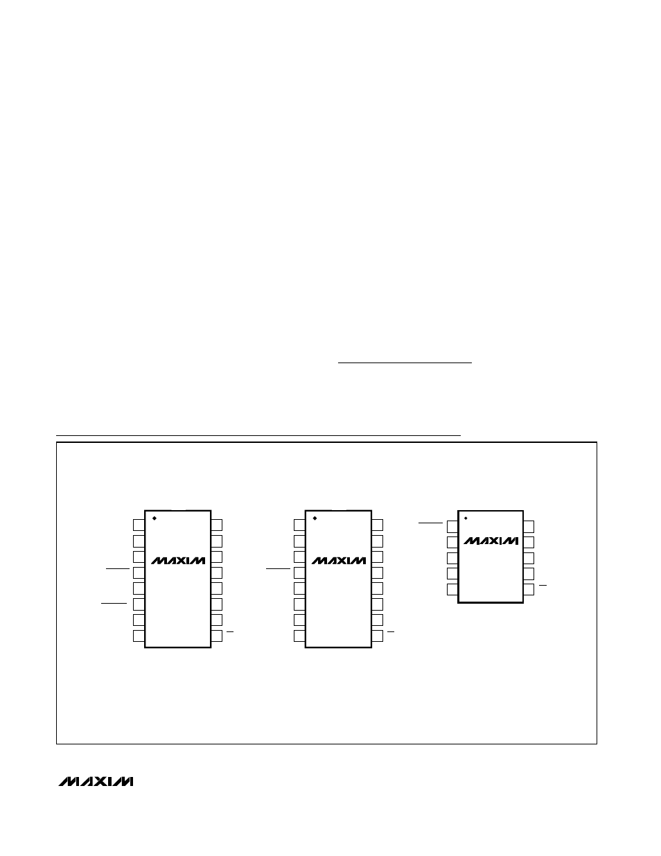
Pin Configurations
16
15
14
13
12
11
10
9
1
2
3
4
5
6
7
8
TH1
V
DD
TH2
OT1
OT2
PWM_OUT
FAN_IN1
FAN_IN2
OT
TOP VIEW
MAX6643_A _
MAX6643_B_
QSOP
TL2
TL1
FULLSPD
(FULLSPD)
FANFAIL
TACHSET
GND
DXP
16
15
14
13
12
11
10
9
1
2
3
4
5
6
7
8
TH1
V
DD
TH2
OT1
OT2
PWM_OUT
FAN_IN1
FAN_IN2
OT
MAX6644_ _
QSOP
TL2
TL1
DXP2
FANFAIL
TACHSET
GND
DXP1
1
2
3
4
5
10
9
8
7
6
V
DD
PWM_OUT
FAN_IN1
FAN_IN2
GND
DXP2
TACHSET
FANFAIL
MAX6645_ _
µ
MAX
OT
DXP1
() ARE FOR MAX6643_A ONLY.