Rainbow Electronics MAX5157 User Manual
Page 15
Digital Calibration and
Threshold Selection
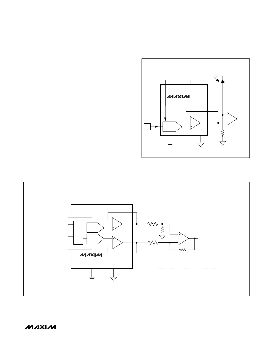
Figure 13 shows the MAX5156/MAX5157 in a digital
calibration application. With a bright value applied to
the photodiode (on), the DAC is digitally ramped up
until it trips the comparator. The microprocessor stores
this high calibration value. Repeat the process with a
dim light (off) to obtain the dark current calibration. The
microprocessor then programs the DAC to set an out-
put voltage that is the midpoint of the two calibration
values. Applications include tachometers, motion sens-
ing, automatic readers, and liquid clarity analysis.
Digital Control of Gain and Offset
The two DACs can be used to control the offset and
gain for curve-fitting nonlinear functions, such as trans-
ducer linearization or analog compression/expansion
applications. The input signal is used as the reference
for the gain-adjust DAC, whose output is summed with
the output from the offset-adjust DAC. The relative
weight of each DAC output is adjusted by R1, R2, R3,
and R4 (Figure 14).
MAX5156/MAX5157
Low-Power, Dual, 12-Bit Voltage-Output DACs
with Configurable Outputs
______________________________________________________________________________________
15
AGND
DIN
µ
P
DGND
MAX5156
MAX5157
DAC _
REF_
OUT_
R
FB_
V+
V-
PHOTODIODE
V+
V
DD
V
OUT
+5V/+3V
Figure 13. Digital Calibration
AGND
DGND
REFA
CONTROL/
SHIFT REGISTER
REFB
MAX5156
MAX5157
DACA
+5V/+3V
V
DD
V
IN
CS
DIN
SCLK
CL
V
REF
R1
R3
R4
R2
OUT_B
FBB
FBA
OUT_A
V
OUT
DACB
=
NA
4096
NA IS THE NUMERIC VALUE OF THE INPUT CODE FOR DACA.
NB IS THE NUMERIC VALUE OF THE INPUT CODE FOR DACB.
R2
R1+R2
R4
R3
NB
4096
R4
R3
(
V
IN
)(
)(
1+
) (
V
REF
)( )
V
OUT
=
[
GAIN
]
-
[
OFFSET
]
[ ] [ ]
Figure 14. Digital Control of Gain and Offset