Table 1. serial-interface programming commands – Rainbow Electronics MAX5157 User Manual
Page 10
MAX5156/MAX5157
Power-Down Mode
The MAX5156/MAX5157 feature a software-program-
mable shutdown mode that reduces the typical supply
current to 2µA. The two DACs can be shut down inde-
pendently or simultaneously by using the appropriate
programming word. For instance, enter shutdown mode
(for both DACs) by writing an input control word of
111XXXXXXXXXXXX0 (Table 1). In shutdown mode, the
reference inputs and amplifier outputs become high
impedance, and the serial interface remains active.
Data in the input registers is saved, allowing the
MAX5156/MAX5157 to recall the output state prior to
entering shutdown when returning to normal mode. Exit
shutdown by recalling the previous condition or by
updating the DAC with new information. When returning
to normal operation (exiting shutdown), wait 20µs for
output stabilization.
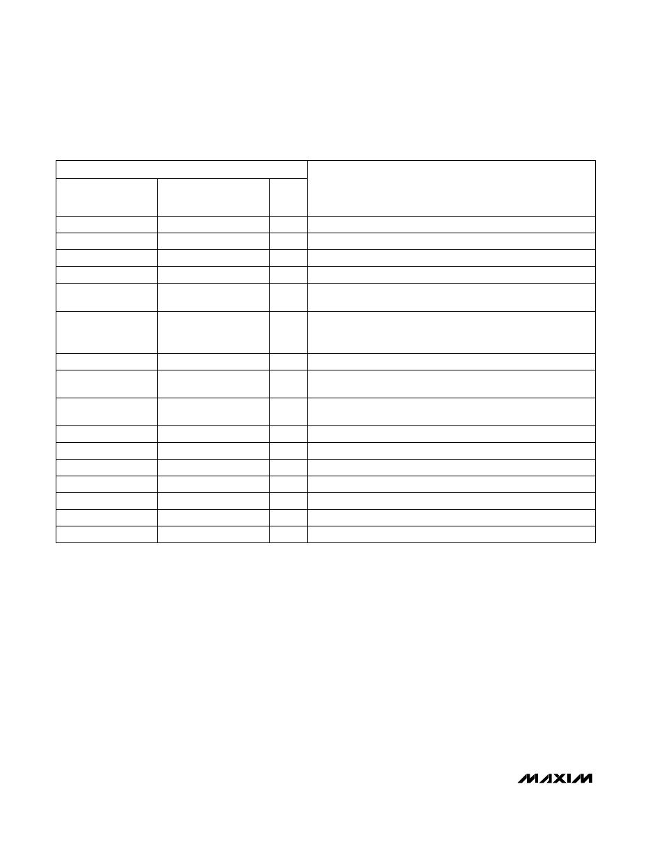
Serial Interface
The MAX5156/MAX5157 3-wire serial interface is com-
patible with both Microwire (Figure 2) and SPI/QSPI
(Figure 3) serial-interface standards. The 16-bit serial
input word consists of an address bit, two control bits,
12 bits of data (MSB to LSB), and one sub bit as shown
in Figure 4. The address and control bits determine the
response of the MAX5156/MAX5157, as outlined in
Table 1.
Low-Power, Dual, 12-Bit Voltage-Output DACs
with Configurable Outputs
10
______________________________________________________________________________________
D 1 1 . . . . . . . . . . . . . . . . D 0
MSB
LSB
FUNCTION
A0
C1
C0
0 0 1
12 bits of DAC data
Load input register A; DAC register is unchanged.
0 1 1
12 bits of DAC data
Load all DAC registers from the shift register (start up both DACs
with new data).
1 1 0
12 bits of DAC data
Load input register B; all DAC registers are updated.
0 1 0
12 bits of DAC data
Load input register A; all DAC registers are updated.
1 0 1
12 bits of DAC data
Load input register B; DAC register is unchanged.
0 0 0
1 1 0 x xxxxxxxx
Shut down DAC A when PDL = 1.
0 0 0
1 0 1 x xxxxxxxx
Update DAC register B from input register B (start up DAC B with
data previously stored in input register B).
0 0 0
0 0 1 x xxxxxxxx
Update DAC register A from input register A (start up DAC A with
data previously stored in input register A).
1 1 1
xxxxxxxxxxxx
Shut down both DACs if PDL = 1.
1 0 0
xxxxxxxxxxxx
Update both DAC registers from their respective input registers
(start up both DACs with data previously stored in the input
registers).
0 0 0
1 1 1 x xxxxxxxx
Shut down DAC B when PDL = 1.
0 0 0
0 1 0 x xxxxxxxx
UPO goes low (default).
0 0 0
0 1 1 x xxxxxxxx
UPO goes high.
0 0 0
1 0 0 1 xxxxxxxx
Mode 1, DOUT clocked out on SCLK’s rising edge.
0 0 0
1 0 0 0 xxxxxxxx
Mode 0, DOUT clocked out on SCLK’s falling edge (default).
0 0 0
0 0 0 x xxxxxxxx
No operation (NOP).
Table 1. Serial-Interface Programming Commands
“x” = don’t care
Note:
D11, D10, D9, and D8 become control bits when A0, C1, and C0 = 0. S0 is a sub bit, always zero.
S0
0
0
0
0
0
0
0
0
0
0
0
0
0
0
0
0
16-BIT SERIAL WORD