Pin description – Rainbow Electronics MAX5079 User Manual
Page 8
MAX5079
ORing MOSFET Controller with
Ultra-Fast 200ns Turn-Off
8
_______________________________________________________________________________________
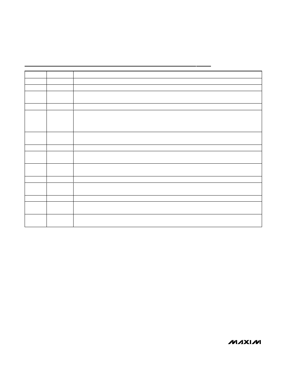
Pin Description
PIN
NAME
FUNCTION
1
CXN
Negative Terminal of External Flying Charge-Pump Capacitor
2
CXP
Positive Terminal of External Flying Charge-Pump Capacitor
3
OVP
Open-Drain Active-Low Output. OVP sinks up to 10mA when V
OVI
≥ 0.6V and V
IN
≥ V
BUS
. OVP can be
used to drive an optodiode. Cycle power or pull UVLO low and then high to reset OVP.
4
PGOOD
Open-Drain Active-Low Output. PGOOD pulls low when V
UVLO
≤ 0.6V or V
OVI
≥ 0.6V.
5
STH
ORing MOSFET Slow-Comparator Reverse Voltage Threshold and Blanking Time Setting Input. Connect
a resistor from STH to GND to set the threshold. Connect a capacitor from STH to GND to set the
blanking time. Leave STH floating to set the internal threshold (-12mV) and internal blanking time
(0.9ms).
6
FTH
Fast-Comparator Reverse Threshold Setting. Connect a resistor from FTH to GND to set the fast-
comparator reverse voltage threshold from -24mV to -400mV.
7
OVI
Overvoltage Comparator Input. Connect OVI to BUS through a resistive divider.
8
UVLO
Undervoltage Lockout Comparator Input. Connect UVLO to IN through a resistive divider. The MAX5079
remains off until V
UVLO
rises above 0.66V. When V
UVLO
rises above 0.664V, V
GATE
is raised to V
IN
.
9
PGND
Power Ground. Ground discharge path of the 2A GATE pulldown. Connect to external power ground
plane.
10
GATE
Gate-Driver Output for n-Channel ORing MOSFET
11
BUS
Bus Voltage-Sense Input. Connect BUS to the drain of the ORing MOSFET to sense the polarity of the
Bus Current. The MAX5079 receives its power from BUS when V
IN
and V
AUXIN
are not present.
12
GND
Signal Ground. Connect to the low-level signal or analog ground.
13
IN
Source Connection for ORing MOSFET and Supply Input for the MAX5079. Connect IN directly to the
power-supply voltage of 2.75V to 13.2V or 1V to 13.2V with V
AUXIN
≥ 2.75V.
14
AUXIN
Auxiliary Power-Supply Input. AUXIN supplies power to the IC when 1V
≤ V
IN
≤ 2.75V. Connect AUXIN to
2.75V or higher if V
IN
is less than 2.75V.