Selector guide, Chip information, Functional diagram – Rainbow Electronics MAX15001 User Manual
Page 17
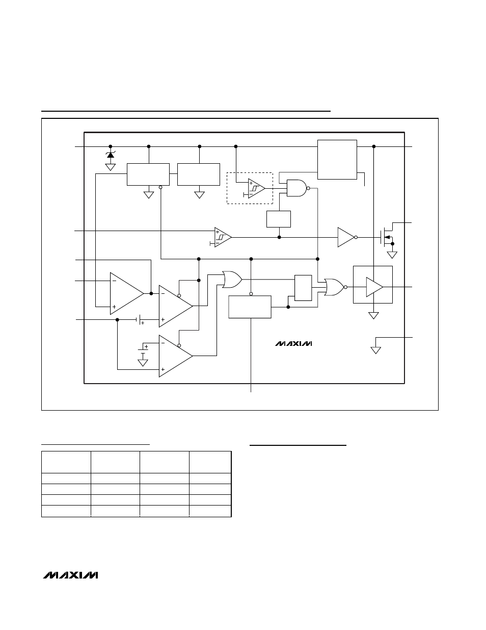
MAX15000/MAX15001
Current-Mode PWM Controllers with
Programmable Switching Frequency
______________________________________________________________________________________
17
Selector Guide
*The MAX15001 does not have an internal bootstrap UVLO. The
MAX15001 starts operation as long as V
IN
is higher than 9.5V
and UVLO/EN is higher than 1.23V.
PART
BOOTSTRAP
UVLO
STARTUP
VOLTAGE (V)
MAX DUTY
CYCLE (%)
MAX15000A
Yes
22
50
MAX15000B
Yes
22
75
MAX15001A*
No
9.5
50
MAX15001B*
No
9.5
75
Chip Information
PROCESS: BiCMOS
DRIVER
FB
CS
NDRV
GND
IN
COMP
UVLO/EN
IN
CLAMP
26.1V
*MAX15000 ONLY
*
UFLG
V
CC
MAX15000
MAX15001
ERROR
AMP
CPWM
UVLO
RT
OSCILLATOR
ILIM
S
R
REG_OK
REGULATOR
(INTERNAL 5.25V
SUPPLY)
IN
V
L
V
CC
Q
1.23V
1.17V
V
CS
1V
1.4V
DIGITAL
SOFT-START
REFERENCE
1.23V
N
210
µs
DELAY
BOOTSTRAP UVLO
21.6V
9.74V
Functional Diagram
- MAX5151 (16 pages)
- MAXQ3108 (64 pages)
- MAX5661 (39 pages)
- MAX6691 (7 pages)
- MAX5362 (12 pages)
- ADC10158 (26 pages)
- MAX8922L (14 pages)
- MAX8596Z (8 pages)
- MAX7491 (18 pages)
- MAX15040 (15 pages)
- MAX5177 (16 pages)
- ADC08138 (22 pages)
- MAX5961 (42 pages)
- T89C51RD2 (86 pages)
- MAX16055 (9 pages)
- MAX6659 (17 pages)
- ADC0820 (20 pages)
- MAX6678 (19 pages)
- MAX8884Z (15 pages)
- MAX16915 (9 pages)
- MAX8620 (18 pages)
- MAX5144 (12 pages)
- MAX6670 (8 pages)
- MAX8760 (39 pages)
- W78C32C (14 pages)
- MX7533 (8 pages)
- MAX8727 (13 pages)
- MAX9053 (15 pages)
- W78C54 (16 pages)
- MAX8614B (15 pages)
- W90N740 (219 pages)
- MAX6626 (13 pages)
- ADC10738 (30 pages)
- MAX17000 (31 pages)
- MAX5051 (21 pages)
- MAXQ1004 (18 pages)
- MAX6871 (51 pages)
- MX7847 (12 pages)
- MAX6608 (6 pages)
- MAX17083 (15 pages)
- MAX6641 (17 pages)
- MAX5251 (16 pages)
- MAX6338 (8 pages)
- MAX6690 (16 pages)
- MAX8668 (18 pages)