Rld65mzt2, Laser diodes – Rainbow Electronics RLD65MZT2 User Manual
Page 2
RLD65MZT2
Laser Diodes
2/2
!
!
!
!
Absolute maximum ratings (Tc=25
°C)
Parameter
P
O
V
R
V
R(PIN)
Tstg
Topr
mW
V
V
Symbol
10
2
30
−
10 to
+
70
−
40 to
+
85
Limits
Unit
°
C
°
C
Output
Raser
Operating temperature
Storage temperature
PIN photodiode
Reverse
voltage
!
!
!
!
Electrical and optical characteristics (Tc=25
°C)
Parameter
Symbol
Min.
Typ.
Max.
Unit
Conditions
I
th
mA
−
25
60
−
−
I
op
mA
−
35
70
P
O
=
5mW
P
O
=
5mW
P
O
=
5mW
P
O
=
5mW
P
O
=
5mW
P
O
=
5mW
P
O
=
5mW
I
m
mA
0.1
0.2
0.5
θ
//
∗
deg
7
8
10
θ
⊥
∗
deg
20
27
35
∆φ
//
deg
−
2
0
+
2
λ
nm
645
655
660
P
O
=
5mW
Astigmatism
∆
µ
m
−
−
10
P
O
=
5mW
∆φ
⊥
deg
−
3
0
+
3
∆
Y
∆
Z
∆
X
µ
m
−
80
0
+
80
−
V
op
V
−
2.3
2.6
η
mW/mA
0.2
0.4
0.8
∗
θ
//
and
θ
⊥
are defined as the angle within which the intensity is 50% of the peak value.
Threshold current
Operating current
Monitor current
Parallel divergence angle
Perpendicular divergence angle
Parallel deviation angle
Peak emission wavelength
Perpendicular deviation angle
Emission point accuracy
Operating voltage
Differential efficiency
!
!
!
!
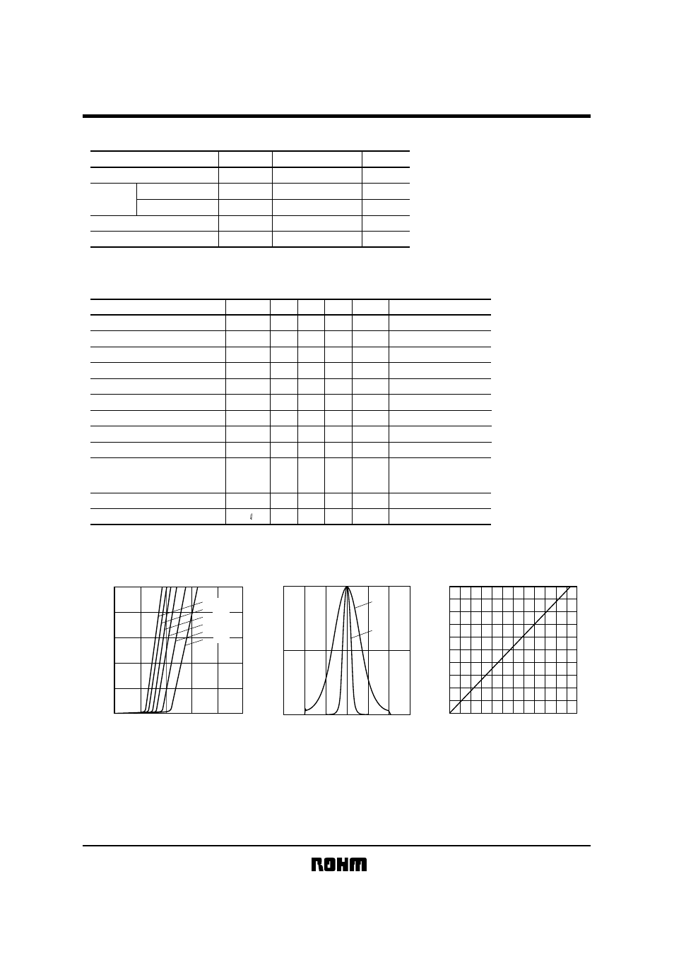
Electrical and optical characteristics curves
10
8
6
2
4
0
0
20
40
60
80
100
OPTICAL PO
WER :
P
O
(mW)
OPERATING CURRENT : Iop
(mA)
Tc
=
25
°
C
40
°
C
50
°
C
60
°
C
70
°
C
80
°
C
Fig.1 Optical output
vs. operating current
1.0
0.5
0
−
60
−
40
−
20
0
60
40
20
INTENSITY
ANGLE (
deg)
θ
⊥
θ
//
Fig.2 Far field pattern
10
1
2
3
4
5
6
7
8
9
0
0
0.1
0.2
0.3
OPTICAL INTENSITY :
P
O
(mW)
MONITOR CURRENT : I
m
(mA)
Fig.3 Monitor current
vs. optical output