Ready – Rainbow Electronics MAX5139 User Manual
Page 11
MAX5138/MAX5139
Low-Power, Single, 16-/12-Bit,
Buffered Voltage-Output DACs
______________________________________________________________________________________
11
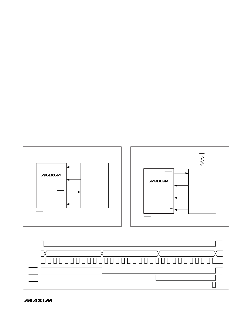
SCLK
DIN
READY*
CS
SI*
I/O
SO
SK
MICROWIRE
PORT
*THE READY-TO-SI CONNECTION IS NOT REQUIRED FOR WRITING TO THE
*
MAX5138/MAX5139 BUT MAY BE USED FOR TRANSMISSION VERIFICATION.
MAX5138
MAX5139
Figure 2. Connections for MICROWIRE
The MAX5138’s DAC code is unipolar binary with V
OUT
= (code/65536) x V
REF
. See Table 1 for the serial inter-
face commands.
The MAX5139’s DAC code is unipolar with V
OUT
=
(code/4096) x V
REF
. See Table 1 for the serial interface
commands.
Connect the MAX5138/MAX5139 DVDD supply to the
supply of the host DSP or microprocessor. The AVDD
supply may be set to any voltage within the 2.7V to
5.25V operating range, but must be greater than or
equal to the DVDD supply.
Writing to the MAX5138/MAX5139
Write to the MAX5138/MAX5139 using the following
sequence:
1) Drive CS low, enabling the shift register.
2) Clock 24 bits of data into DIN (C7 first and D0 last),
observing the specified setup and hold times. Bits
D15–D0 are the data bits that are written to the
internal register.
3) After clocking in the last data bit, drive CS high. CS
must remain high for 33ns before the next transmis-
sion is started.
Figure 1 shows a write operation for the transmission of
24 bits. If CS is driven high at any point prior to receiving
24 bits, the transmission is discarded.
READY
Connect READY to a microcontroller (µC) input to moni-
tor the serial interface for valid communications. The
READY pulse appears 24 clock cycles after the nega-
tive edge of CS (Figure 4). Since the MAX5138/
MAX5139 look at the first 24 bits of the transmission fol-
lowing the falling edge of CS, it is possible to daisy
chain devices with different command word lengths.
READY goes high 16ns after CS is driven high.
READY*
DIN
SCLK
CS
SCK
SS
I/O
MOSI
+5V
MISO*
SPI/QSPI
PORT
*THE READY-TO-MISO CONNECTION IS NOT REQUIRED FOR WRITING TO THE
MAX5138/MAX5139 BUT MAY BE USED FOR TRANSMISSION VERIFICATION.
MAX5138
MAX5139
Figure 3. Connections for SPI/QSPI
CS
DIN
SCLK
READY 1
READY 3
READY 2
1
23
24
22
21
20
4
3
2
1
23
24
22
21
5
4
3
2
1
23
24
22
21
5
4
3
2
SLAVE 1 DATA
SLAVE 2 DATA
SLAVE 3 DATA
Figure 4. READY Timing