Applications information, Table 1. power-down mode selection – Rainbow Electronics MAX5184 User Manual
Page 10
MAX5181/MAX5184
10-Bit, 40MHz, Current/Voltage-Output DACs
10
______________________________________________________________________________________
Applications Information
Static and Dynamic
Performance Definitions
Integral Nonlinearity
Integral nonlinearity (INL) (Figure 5a) is the deviation of
the values on an actual transfer function from either a
best-straight-line fit (closest approximation to the actual
transfer curve) or a line drawn between the endpoints
of the transfer function once offset and gain errors have
been nullified. For a DAC, the deviations are measured
every single step.
Differential Nonlinearity
Differential nonlinearity (DNL) (Figure 5b) is the differ-
ence between an actual step height and the ideal value
of 1LSB. A DNL error specification of less than 1LSB
guarantees no missing codes and a monotonic transfer
function.
Table 1. Power-Down Mode Selection
X = Don’t care
9.6k*
I
FS
0.1
µF
10
µF
DV
DD
R
SET
REFR
AV
DD
REFO
+1.2V
BANDGAP
REFERENCE
REN
DGND
AGND
AGND
CURRENT-
SOURCE ARRAY
EXTERNAL
+1.2V
REFERENCE
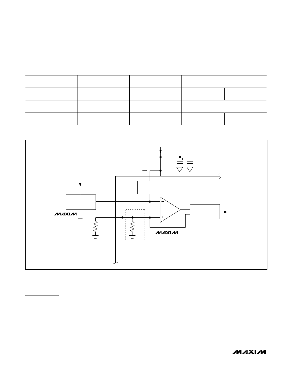
*9.6k
Ω REFERENCE CURRENT-SET RESISTOR
INTERNAL TO MAX5184 ONLY. USE EXTERNAL
R
SET
FOR MAX5181.
MAX5181
MAX5184
MAX6520
Figure 3. MAX5181/MAX5184 with External Reference
Wake-Up
High-Z
High-Z
MAX5181
MAX5181
AGND
MAX5184
Shutdown
X
1
Last state prior to standby mode
1
0
AGND
MAX5184
Standby
0
0
OUTPUT STATE
POWER-DOWN MODE
DACEN (DAC ENABLE)
PD
(POWER-DOWN SELECT)